Thursday, August 30, 2018

Troubleshooting Dial-up T1 Lines

I had an interesting trouble ticket land in my lap a few years ago.  My employer at the time was one of the few service providers still using various and sundry Cisco AS5300 routers to provide dial-up (!) Internet service to customers.  In one location where we had one of these AS5300 routers, the CO tech was notified that his telephone switch was seeing "Remote Made Busy" alarms from my AS5300, and after some initial troubleshooting, he escalated the ticket to me to investigate from the router side.

Unfortunately, when I logged in to the router, I found nothing wrong:
as2.blah#sho run | begin controller
controller T1 0
framing esf
clock source line primary
linecode b8zs
cablelength short 133
ds0-group 0 timeslots 1-24 type e&m-fgb dtmf dnis
description HC 09201 tg#ISP2 trk 1-24, DTC 00-07, #xxx-1005
!
as2.blah#sho controller t1 0
T1 0 is up.
  Applique type is Channelized T1
  Cablelength is short 133
  Description: HC 09201 tg#ISP2 trk 1-24, DTC 00-07, #xxx-1005
  No alarms detected.
  alarm-trigger is not set
  Version info of slot 0:  HW: 1, PLD Rev: 11
  Framer Version: 0x8
<...snip...>
  Total Data (last 24 hours)
     1 Line Code Violations, 1 Path Code Violations,
     0 Slip Secs, 0 Fr Loss Secs, 1 Line Err Secs, 1 Degraded Mins,
     1 Errored Secs, 0 Bursty Err Secs, 0 Severely Err Secs, 0 Unavail Secs
as2.blah#sho caller ip
  Line           User       IP Address      Local Number    Remote Number   <->
as2.blah#

You can manually busy-out a trunk, as shown on Controller T1 2:
as2.blah#sho run | begin ontroller
<...snip...> controller T1 2
framing esf
clock source line secondary 2
linecode b8zs
cablelength short 133
ds0-group 0 timeslots 1-24 type e&m-fgb dtmf dnis
ds0 busyout 1-24 soft
description 45.ISP.001119..8901 tg#ISP2 trk 49-72, DTC 04-01, #xxx-4108/xxx-1199
!
<...snip...>

See the line that says, "ds0 busyout 1-24 soft?"  That tells the router to busy-out (disable, but only once an individual DS-0 goes inactive) the individual voice channels inside the T1.  However, that line didn't exist on Controller T1 0, so no-one had intentionally busied-out the trunk.

Once I had verified that there was nothing obviously wrong with the T1, I bounced the T1 line by running a shut/no shut on Controller T1 0.  No change.  Then, I rebooted the router.  Again, no change.  I called the CO tech, who confirmed that he was still seeing the "Remote Made Busy" alarm on the T1, meaning that from his equipment's perspective, my router had busied-out the individual lines on the T1.

Eventually, I called a co-worker of mine who had been a Cisco AS5x00 guru back in the day, who showed me another troubleshooting tip:
as2.blah# sho controllers t1 0 call-counters
T1 0:
  DS0's Active: 0
  DS0's Active High Water Mark: 2
  TimeSlot   Type   TotalCalls   TotalDuration
      1       cas           6       00:36:48
      2       cas           7       01:19:29
      3       cas           7       00:24:16
      4       cas           7       00:30:35
      5       cas           7       00:15:49
      6       cas           6       02:33:36
      7       cas           7       03:06:59
      8       cas           7       00:23:25
      9       cas           7       03:01:43
     10       cas           5       04:03:10
     11       cas           6       00:38:36
     12       cas           7       01:08:50
     13       cas           5       05:33:33
     14       cas           6       01:36:16
     15       cas           5       00:16:07
     16       cas           6       01:06:34
     17       cas           5       01:06:48
     18       cas           5       00:09:15
     19       cas           6       00:05:20
     20       cas           6       02:12:24
     21       cas           6       01:25:18
     22       cas           5       00:27:50
     23       cas           5       00:42:23
     24       cas           6       01:47:45

Total DS0's Active High Water Mark: 3
Total Calls since System Bootup: 178
as2.blah#

Ideally, under the "TotalCalls" column, we would see an even distribution of calls -- that is, each individual timeslot in the T1 trunk would have approximately the same number of received calls -- and in fact, in this case, the distribution turns out to be pretty even, with between 5 and 7 calls on each DS-0 (controller T1 1 looks even better with almost exactly six calls per DS-0).  Also, the last column, "TotalDuration," shouldn't show any unusually low counts, where "unusual" is determined entirely by context.  In this case, the router had been rebooted recently, so fairly low numbers for call duration were to be expected.  However, if most of the individual timeslots had total call durations of 20-30 hours, and one (or two, or...) timeslots had call durations of, say, 30 minutes, then that's a pretty good indication of a problem on that DS-0, especially if the router had not been rebooted in quite a while (the longer it has been running, the more even the call duration distribution should be).

Eventually, the engineer I called agreed with my assessment: there did not appear to be anything wrong with the router or the T1 lines.  Our best guess was that, at some point in the last ten years or so since this router had been installed, our documentation in the controller description had diverged from what was actually plugged in to the router, meaning that controller T1 0 was not the one we really should have been troubleshooting.  Unfortunately, by the time I got that far with the troubleshooting process, the problem had mysteriously corrected itself, and as a result, I didn't get a chance to verify the controller descriptions.  That's a bit of a mixed blessing.  To the engineer in me, it was disappointing not to have found a definitive cause of the problem, but at least everything was working properly once again.

Monday, August 28, 2017

Cisco ASA -- Intro to NAT, Auto NAT and Twice NAT

A couple of years ago, I first started working with Cisco ASA firewalls. One of the things that has driven me nuts about the ASA is how complicated it makes NAT. From my experience with Linux, I was aware of Source NAT, Destination NAT and Masquerading. However, the ASA added several other variations on the theme: Single NAT, Auto NAT, Twice NAT, and most bizarre of all, Identity NAT. Cisco documentation and most other network references I consulted didn't clear things up much (if at all). Since I tend to learn best by being hands-on, I fired up GNS3 and started playing around with an emulated ASA.

First, single NAT. In this scenario, you manually create a NAT translation. In most cases, you have a private network using IP addresses defined in RFC-1918 on the inside of your firewall. Since this address space is not routable on the public Internet, you must rewrite the source address of any packet originating on your private network if you want to reach a host outside of your network. Likewise, if you have a server inside your private network that should be reachable from the Internet, incoming packets must have the destination IP address rewritten as they cross your firewall. This is pretty straightforward on the ASA. Given the following interface configuration...:

interface GigabitEthernet0.10
description INSIDE
vlan 10
nameif INSIDE
security-level 100
ip address 192.168.1.1 255.255.255.0
!
interface GigabitEthernet0.300
description OUTSIDE
vlan 300
nameif OUTSIDE
security-level 0
ip address 100.64.1.53 255.255.255.248
!

Next, we will define the client PC's "real" and "mapped" IP addresses (the IP address actually configured on the client, and the IP address that Internet hosts will see, respectively):

object network CLIENT
host 192.168.1.3
object network CLIENT-OUTSIDE
host 100.64.1.129

Finally, we create the NAT statement to translate the client's real IP to the mapped IP:

nat (INSIDE,OUTSIDE) source static CLIENT CLIENT-OUTSIDE

Now, when the client tries to reach a host on the public Internet, the firewall will rewrite incoming and outgoing packets as described above. To test this, I created a simple CGI script on a web server that displays the "environment variables" passed to the CGI in an HTTP session:


As you can see, the web server sees the client PC's IP address as 100.64.1.3 (okay, yes, technically, that is not a publicly routable IP address either, but is instead a "Carrier-grade NAT" address, a special private IP space address, but even in my labs in GNS-3, I don't like to use real public IP address space). Pretty simple, right?

Next up, Auto NAT (or Object-NAT, IIRC -- if I'm wrong, please leave a comment below!). Object-NAT looks very simple, and in many on-line tutorials I've seen, is described as one of the simplest ways of setting up NAT on a firewall. However, I have found it to be quite finicky, at least on the version of ASA code that I'm using in GNS3. More than once, I have copied an existing config, changing IP addresses and object names as required, but finding one config works while the other does not. Even more frustrating, the ASA code that I'm using in GNS3 is much older than the code I'm using in the real world, and the object-NAT configuration is slightly different between the two versions. Despite these differences, let's give object-NAT a try.

For the object-NAT example, we'll use the following network:


...and the following network objects:

1. The Knoppix Clone's real (RFC-1918) IP address:
object network CLONE-REAL-IP
host 192.168.1.2
!

2. The Knoppix Clone's NAT (i.e., "public") IP address:
object network CLONE-NAT-IP
host 100.64.1.2
!

3. The Knoppix Host's real (RFC-1918) IP address:
object network K32-REAL-IP
host 10.0.0.2
!

4. The Knoppix Host's NAT IP address:
object network K32-NAT-IP
host 100.64.0.2
!

The Knoppix Clone will be on our "inside" network, and Knoppix-32 will be on the "public" network. Yes, I know -- I am using private IP addresses for everything, but just play along, okay? ;) Auto-NAT is sometimes called Object-NAT because the NAT statement exists inside of an "object network ..." statement:
object network CLONE-NAT-IP
nat (Side_B,Side_A) nat (SIDE_B,SIDE_A) source dynamic CLONE-REAL-IP CLONE-NAT-IP
!

Just for giggles, try this after setting up the object NAT shown above:

sho run | begin CLONE-NAT-IP

Most likely, you saw something like this:

object network CLONE-NAT-IP
host 100.64.1.2
object network K32-REAL-IP
host 10.0.0.2
object network K32-NAT-IP
host 100.64.0.2
...

Wait a minute...what happened to our NAT statement? Well, if you keep scrolling, you'll see it somewhere down near the end of the config. For whatever reason, Cisco decided it made sense to break the object definition in two, putting the host (or subnet or range or...) portion in one place in the config and the NAT portion in another </shrug> Don't ask me; I don't know why, either.

In any case, now that the NAT rule has been created, let's try to ping the Knoppix Clone from the Knoppix Host:
        Side_A pings Side_B:
        ping 100.64.1.2

        Side_A tcpdump:
          10.0.0.2 > 100.64.1.2
          10.0.0.2 > 100.64.1.2

        Side_B tcpdump:
...nothing...

Next, we'll try pinging from the Knoppix Clone to the Knoppix Host:
        Side_B pings Side_A:
        ping 10.0.0.2

        Side_A tcpdump:
          100.64.1.2 > 10.0.0.2
          10.0.0.2 > 100.64.1.2

        Side_B tcpdump:
          192.168.1.2 > 10.0.0.2
          10.0.0.2 > 192.168.1.2

Did that make sense? Because this NAT translation only allows traffic to originate on the inside network (established, related packets will always be allowed back in with a stateful firewall), the Knoppix Host cannot ping the Knoppix Clone, but the Knoppix Clone can ping the Knoppix Host.

Things really get interesting, however, with Twice NAT. In this situation, not only do you want to rewrite the IP address of a system on the INSIDE network, but you also want to rewrite the IP address of a system on the OUTSIDE network as well. Why? Well...I don't know. But if for some reason you do, here's how to do it :)

We'll use the same ASA interface configuration that we used in the discussion of Single NAT above.

Next, we'll define the objects used in this config. As in the Single NAT and Auto NAT discussion, we'll use "CLIENT" to mean the host on the inside network and "CLIENT-OUTSIDE" to mean the NAT'd IP address of the client host (the IP that outside hosts see the request coming from). However, we will create two new objects, "MAPPED-DEST" which is the IP address that CLIENT will use in URL's, ping commands, etc. and "REAL-DEST" which is the actual IP address of the host on the OUTSIDE network. In other words, just as "CLIENT" refers to the actual IP address configured on the host on the INSIDE network, "REAL-DEST" refers to the actual IP address configured on host on the OUTSIDE network. Likewise, just like "CLIENT-OUTSIDE"refers to the IP address that OUTSIDE hosts use to reach the INSIDE network, "MAPPED-DEST" refers to the IP address that INSIDE hosts use to reach the OUTSIDE network:

object network MAPPED-DEST
host 172.16.0.1
object network REAL-DEST
host 100.64.1.3

Finally, we create the NAT statement to set up the Twice NAT:

nat (INSIDE,OUTSIDE) source static CLIENT CLIENT-OUTSIDE destination static MAPPED-DEST REAL-DEST

The only difference between this config and the Single NAT config is the addition of "destination static MAPPED-DEST REAL-DEST" at the end of the NAT statement. On the CLIENT computer, we can now try to access the server on the OUTSIDE network using the IP address 172.16.0.1:


As you can see, we are accessing the web server on the outside network by using the IP address 172.16.0.1, even though the IP address on the server is actually 100.64.1.3. Likewise, the web server sees the request coming from 100.64.1.129, even though the client's IP address is actually 192.168.1.3. In other words, we are NAT'ing both the INSIDE and OUTSIDE networks.

For our last example, we'll set up identity-NAT. I have to admit, this twist on NAT really threw me when I first encountered it. "Wait, you mean to tell me that we are creating a NAT rule to rewrite an incoming packet to use the EXACT SAME IP address it originally had?!?!" At first, it does seem a little silly, doesn't it? However, consider this scenario: you have a firewall with an inside and outside network, and you have an object-NAT rule to translate outgoing requests to a pool of publicly routable IP addresses. However, for some reason, there is a host or subnet connected to your outside interface that you wish to access via your private, inside IP addresses. For example, it is possible that in a large enterprise network, you might have firewalls between various departments inside the company. These firewalls might do the NAT translations from RFC-1918 addressing to public addressing, but you might still want to access a resource in another department via your private IP range (that's kinda-sorta the situation with one of the ASA's I currently manage). In this case, the identity-NAT rule will override the object-NAT rule for the objects that you specify. In terms of configuring identity-NAT, it's pretty much the same as single-NAT, except that you use the same source object and destination object in the NAT rule:

object network CLIENT
host 192.168.1.3
object network CLIENT-OUTSIDE
host 100.64.1.129
!
nat (INSIDE,OUTSIDE) source static CLIENT CLIENT

No, that's not a typo -- I really did mean "CLIENT CLIENT" in the NAT rule. Essentially, we are saying, "When a packet comes into the INSIDE interface with the IP address 192.168.1.3, rewrite the packet exiting the OUTSIDE interface with the source IP address of 192.168.1.3. This works because the ASA follows a hierarchy much like the mathematical concept of "order of operations" to determine at what point the various types of NAT will be performed. In this case, the identity NAT will happen after the object-NAT, so the identity-NAT rule will override the object-NAT.

Sunday, January 8, 2017

Advanced Cisco Routing -- BGP MED (Multi-Exit Discriminator)

Suppose we have two connections to our upstream ISP: a high-speed link from Cust-A to ISP-1, and a low-speed link from Cust-A to ISP-2 (Cust-B is just a random Internet host):


Here are the subnets in use on this network:

SubnetEndpoint AEndpoint A InterfaceEndpoint BEndpoint B Interface
10.254.254.1ISP-1Lo0N/AN/A
10.254.254.2ISP-2Lo0N/AN/A
100.64.1.254Cust-ALo0N/AN/A
100.64.2.254Cust-ALo0N/AN/A
10.0.0.0/30ISP-1Gig-E 1/0Cust-AGig-E 1/0
10.0.0.4/30ISP-1Gig-E 2/0Cust-BGig-E 1/0
10.0.0.8/30ISP-1Gig-E 3/0ISP-2Gig-E 3/0
10.0.0.12/30ISP-2Gig-E 1/0Cust-BGig-E 2/0
100.64.1.0/26Cust-AFast-E 0/0Knoppix-32Eth 1/0
100.64.2.0/26Cust-BFast-E 0/0CentOS7_1Eth 1/0

Obviously, we would typically want traffic to flow across the high-speed link rather than the low-speed link. However, BGP doesn't consider bandwidth when determining the "best" path from one host to another:


As you can see, BGP has selected a route via the low-speed circuit from the host Knoppix-32 PC to the CentOS7_1 web server in Cust_B's network. To solve this problem, it's easy enough to set a weight on the outbound link to force traffic to use the circuit connected to ISP-1. All we have to do is set a sufficiently high metric on the route we want to take:

Cust-A
router bgp 65512
neighbor 10.0.0.1 weight 30

Since higher weights take priority over lower weights, this will force outbound traffic to use ISP-1 rather than ISP-2. However, that only has an effect on our outbound traffic. BGP may still provide a route from Cust-B back to us through ISP-2 (the low-bandwidth circuit). This potentially causes two problems: first, we'd rather have our traffic go through the faster circuit (for obvious reasons); and second, this can cause "asymmetric routing." Some applications and network devices (stateful firewalls, for example) really don't like asymmetric routing. Unfortunately, trying to troubleshoot a problem caused by asymmetric routing can be a real PITA, and no, not the tasty kind :( To force other networks to prefer the path via ISP-1, we will adjust BGP's "MED" ("Multi Exit Discriminator"), one of the metrics that BGP uses to calculate the "best" route between endpoints. First, on our router, we'll create an access list to identify our internal networks:

Cust-A(config)#ip access-list standard BGP_Internal_Nets
Cust-A(config-std-nacl)#permit 100.64.1.0 0.0.0.63
Cust-A(config-std-nacl)#permit host 100.64.1.254

Next, we create a route map:

Cust-A(config)#route-map BGP_MED 10
Cust-A(config-route-map)#match ip addr BGP_Internal_Nets
Cust-A(config-route-map)#set metric 110

Finally, we apply the route map to the LESS-PREFERRED neighbor (ISP-2) in our BGP configuration:

Cust-A(config)#router bgp 65512
Cust-A(config-router)#neighbor 172.16.0.1 route-map BGP_MED out
Cust-A(config-router)#exit
Cust-A(config)#exit
Cust-A#clear ip bgp 65511

Unlike weight, a lower MED is preferable to a higher MED, and therefore, by advertising a higher-than-default MED to ISP-2's BGP process, we are effectively telling it to prefer an alternate route to our network.

After BGP re-converges, we should see that both ISP-1 and ISP-2 are using the higher-bandwidth link via ISP-1 to reach 100.64.1.x:

ISP-1#sho ip bgp | inc 65512
*  10.0.0.0/30      10.0.0.2                 0             0 65512 i
*> 100.64.1.0/26    10.0.0.2                 0             0 65512 i
*> 100.64.1.254/32  10.0.0.2                 0             0 65512 i
*  172.16.0.0/30    10.0.0.2                 0             0 65512 i
ISP-1#

...and...:

ISP-2(config)#do sho ip bgp | inc 65512
*>i100.64.1.0/26    10.0.0.2                 0    100      0 65512 i
*                   172.16.0.2             110             0 65512 i
*>i100.64.1.254/32  10.0.0.2                 0    100      0 65512 i
*                   172.16.0.2             110             0 65512 i
ISP-2(config)#

Perfect! Both routers are now advertising a preferred route via ISP-1, just as we wanted (">" indicates a preferred route). You can verify this by a traceroute from CentOS7_1:


By setting the MED in our BGP config, we have redundant links to our ISP, but will still prefer the high-bandwidth circuit unless there is a problem. I'll leave testing fail-over as an exercise for the reader ;)

Advanced Cisco Routing -- BGP and OSPF Part 2

Quite a while ago, I created a post on using BGP and OSPF together on Cisco routers. In that particular example, I used OSPF to route within an internal area and BGP to peer with another provider's area, then redistributed OSPF into BGP and BGP into OSPF. If you'll recall, one of the reasons I gave for using BGP when service providers peer with each other is that the Internet's routing tables are too large to incorporate into an interior gateway protocol like OSPF.

This raises a question, however. How can you redistribute BGP into OSPF if OSPF isn't capable of handling that many routes?

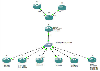
In this lab, I'll show one way of addressing this problem. We'll start by creating the following network:


Warning: I am using publicly routable addresses in this lab! DO NOT try to build this lab on real hardware that is connected to an actual Internet connection, as the potential exists to conflict with real IP addresses actually in use, or to propagate bogus routes into your network!

In this lab, the routers R1 through R6, the routers below the switch in the diagram, are all maintained by various other service providers, and therefore all exist in separate Autonomous Systems (AS's). Meanwhile, the routers above the switch, that is, R7 through R10, are under your control. Because I'm lazy (I've mentioned that before, haven't I?), I simply used loopback interfaces on R1 through R6 to simulate various networks in use on each of the AS's 65512 through 65517. Here is the relevant portions of the config from one of these routers:

interface Loopback0
ip address 141.5.17.1 255.255.255.192
!
interface Loopback1
ip address 141.5.17.65 255.255.255.192
!
interface Loopback2
ip address 141.5.17.129 255.255.255.192
!
interface FastEthernet0/0
ip address 7.7.7.2 255.255.255.240
duplex auto
speed auto
!
router bgp 65513
no synchronization
bgp router-id 141.5.17.1
bgp log-neighbor-changes
network 7.7.7.0 mask 255.255.255.240
network 141.5.17.0 mask 255.255.255.192
network 141.5.17.64 mask 255.255.255.192
network 141.5.17.128 mask 255.255.255.192
neighbor 7.7.7.1 remote-as 65512
neighbor 7.7.7.3 remote-as 65514
neighbor 7.7.7.4 remote-as 65515
neighbor 7.7.7.5 remote-as 65516
neighbor 7.7.7.6 remote-as 65517
neighbor 7.7.7.7 remote-as 65518
no auto-summary
!

One thing I didn't mention in my earlier posts on BGP: the "network" statement in BGP does not operate like the "network" statement in IGP's like OSPF or EIGRP. In this case, the network statement tells BGP what networks you wish to advertise; in an IGP, they enable the routing protocol on the interface that is attached to that network. Consequently, this router (R2, as it happens) is advertising three /26 networks: 141.5.17.0/26, 141.5.17.64/26 and 141.5.17.128/26. It is also offering to peer with six neighbor routers, 7.7.7.1, 7.7.7.3, 7.7.7.4, 7.7.7.5, 7.7.7.6 and 7.7.7.7. So far, pretty straightforward, right?

Likewise, R9 and R10 are pretty straightforward, as well. R8, R9 and R10 are all participating in OSPF area 0.0.0.0:
interface Loopback0
ip address 10.254.254.10 255.255.255.255
!
interface FastEthernet0/0
ip address 194.0.0.10 255.255.255.0
duplex auto
speed auto
!
router ospf 42
router-id 10.254.254.10
log-adjacency-changes
redistribute connected subnets
network 194.0.0.0 0.0.0.255 area 0.0.0.0
!

Again, no surprises here. OSPF is enabled on Fa0/0, and we are redistributing the IP address of our Loopback0 interface in OSPF.

The magic in this lab happens between R7 and R8. In fact, at first glance, you might be wondering why we even put two separate routers here. Since the MTBF of a system of devices decreases with every (non-redundant) device you add to the system (because the probability of a failure of the system is equal to the product of the probability of failure of every non-redundant device in the system), putting two routers in series at this point has decreased the reliability of the network.

The reason for using two routers becomes apparent, however, when you look at the configs:

R7:
interface Loopback0
ip address 10.254.254.7 255.255.255.255
!
interface FastEthernet0/0
ip address 7.7.7.7 255.255.255.240
duplex auto
speed auto
!
interface FastEthernet1/0
ip address 209.112.170.7 255.255.255.0
duplex auto
speed auto
!
router bgp 65518
bgp router-id 10.254.254.7
bgp log-neighbor-changes
neighbor 7.7.7.1 remote-as 65512
neighbor 7.7.7.2 remote-as 65513
neighbor 7.7.7.3 remote-as 65514
neighbor 7.7.7.4 remote-as 65515
neighbor 7.7.7.5 remote-as 65516
neighbor 7.7.7.6 remote-as 65517
neighbor 209.112.170.8 remote-as 65518
!
address-family ipv4
neighbor 7.7.7.1 activate
neighbor 7.7.7.2 activate
neighbor 7.7.7.3 activate
neighbor 7.7.7.4 activate
neighbor 7.7.7.5 activate
neighbor 7.7.7.6 activate
neighbor 209.112.170.8 activate
no auto-summary
no synchronization
network 7.7.7.0 mask 255.255.255.240
network 209.112.170.0
exit-address-family
!

R8:
interface Loopback0
ip address 10.254.254.8 255.255.255.255
!
interface FastEthernet0/0
ip address 209.112.170.8 255.255.255.0
duplex auto
speed auto
!
interface FastEthernet1/0
ip address 194.0.0.8 255.255.255.0
duplex auto
speed auto
!
interface FastEthernet2/0
ip address 193.0.0.8 255.255.255.0
duplex auto
speed auto
!
router ospf 42
router-id 10.254.254.8
log-adjacency-changes
passive-interface Loopback0
network 193.0.0.0 0.0.0.255 area 0.0.0.0
network 194.0.0.0 0.0.0.255 area 0.0.0.0
default-information originate always
!
router bgp 65518
bgp router-id 10.254.254.8
bgp log-neighbor-changes
neighbor 209.112.170.7 remote-as 65518
!
address-family ipv4
neighbor 209.112.170.7 activate
no auto-summary
no synchronization
network 193.0.0.0
network 194.0.0.0
network 209.112.170.0
exit-address-family
!
ip route 0.0.0.0 0.0.0.0 209.112.170.7
!

I don't want to redistribute BGP into OSPF, since that would make the OSPF routing tables too large (okay, not in this example, but if you are peering with actual service providers...). However, I can't just point static routes at the peers either, since that would entirely defeat the purpose of using dynamic routing protocols. Consequently, on R8, I am redistributing OSPF into BGP, then pointing a single default route to R7 and redistributing that default route to R9 and R10 with the "default-information originate" directive on R8. Then, R7 and R8 are BGP peering so that R7 picks up all of the routes in use by R8, R9 and R10 (this is a use of BGP, which is typically an Exterior Gateway Protocol, as an IGP). Because R7 is BGP peering with R1 through R6, it knows how to reach each of the subnets advertised by its peers, and consequently, all of our routers can pass traffic back and forth to each other.

Saturday, January 7, 2017

Advanced Cisco Networking: Policy-Based Routing (PBR)

Suppose you have a multi-homed network where you want to direct certain traffic out one interface, but other traffic out another. For example, maybe you want your VoIP traffic to use a moderately low bandwidth circuit, but with extremely strict QoS policies to provide low latency and jitter, while your bulk data traffic takes a higher bandwidth circuit with no QoS protection. Or, perhaps you have a small-bandwidth circuit for management traffic (one network I managed had an "overhead" T1 on an OC-3 microwave shot and we used the overhead T1 for out-of-band management). In any case, Policy-Based Routing (PBR) is a way for you to designate specific routes for certain traffic, based upon any of a number of characteristics -- basically, if you can match it with an access-list, you can use it to make PBR decisions.

Once again, we'll start with a network diagram:


I've stacked the deck pretty heavily in favor of the route R1-R3-R5 in this network: this route has Gig-E interfaces, while R1-R2-R4-R5 is only using FastEthernet interfaces, and there are fewer hops via R1-R3-R5 than R1-R2-R4-R5. As you can see in the screenshot below, this network design does, in fact, favor using R1-R3-R5 as the preferred route between the two hosts connected to R1 and the CentOS server connected to R5:


Now, let's set up policy-based routing so that system management traffic (Telnet, SSH and SNMP), as well as any traffic from the Sysmon CentOS server are routed through the lower-bandwidth -- but lower latency -- route across R2 and R4:

R1:
R1(config)#ip access-list extended matchSYSMON
R1(config-ext-nacl)#permit tcp any any eq 22
R1(config-ext-nacl)#permit tcp any any eq 23
R1(config-ext-nacl)#permit tcp any any eq 161
R1(config-ext-nacl)#permit ip host 192.168.1.4 any
R1(config-ext-nacl)#deny ip any any
R1(config-ext-nacl)#route-map SYSMON permit 10
R1(config-route-map)#match ip address matchSYSMON
R1(config-route-map)#set ip next-hop 10.1.2.2
R1(config-route-map)#int fa0/0
R1(config-if)#ip policy route-map SYSMON
R1(config-if)#exit

Now, let's try the traceroutes again:


Looks like it did before. However, from Sysmon, we see that we are taking a different route, just as expected:


Since the Knoppix host is simply using the default route, OSPF is using the higher-bandwidth, lower hop-count route. However, the router has identified the traffic originating on the Sysmon server as matching the routing policy that we added to R1, and therefore is steering this traffic through R2 and R4, just as we intended.

If you'll recall, our design goal in this scenario was to ensure that management traffic had low-latency queueing across the network. Suppose our service provider on the R1-R2-R4-R5 path had agreed to honor our QoS markings, but the provider on the R1-R3-R5 path re-marked everything with a lower priority. We can use the route-map we have created for the routing policy to also adjust our QoS markings for traffic going through R2 and R4:

R1(config)#route-map SYSMON permit 10
R1(config-route-map)#match ip address matchSYSMON
R1(config-route-map)#set ip next-hop 10.1.2.2
R1(config-route-map)#set ip precedence flash
R1(config-route-map)#exit
R1(config)#do sho run | section route-map SYSMON permit 10
route-map SYSMON permit 10
match ip address matchSYSMON
set ip precedence flash
set ip next-hop 10.1.2.2
R1(config)#

Cool! Suppose we wanted to do some traffic engineering across an MPLS network:

R1(config)#route-map SYSMON permit 10
R1(config-route-map)#match ip address matchSYSMON
R1(config-route-map)#set ip ?
...
  vrf         VRF name
R1(config-route-map)#

That's really cool! As you can see, policy-based routing is a very powerful tool, allowing you to do a lot of traffic manipulation to optimize your network and traffic flows.

At this point, those of you who are paying attention ;) will be thinking to yourself, "That's great, but what happens if we lose the next-hop router specified in our routing policy?" That is a great question, and with the configuration shown here, your traffic will be dropped on the floor. That's hardly optimal, but as I'm sure you've suspected, there is a solution to this problem...which we'll cover in a later lesson.

Monday, December 19, 2016

Advanced Cisco Routing: BGP Route Reflectors

Advanced Cisco Routing: BGP Route Reflectors Suppose your network uses BGP as your Interior Gateway Protocol (IGP). Because iBGP will not share routes learned across one interface through a second interface (i.e., if R1 learns a route from R2, it will not share that route with R3, R4 or R5), your network must be a full mesh, like so:


While this is very robust, it is neither scalable nor efficient. Given a network of n nodes, then you must create n(n - 1) physical connections, with an IP address on each side of the connection, with a "neighbor ... remote-as..." and "neighbor ... activate" statement in the BGP config, and a "network ... mask ..." statement in the BGP config. When you are talking about just a handful of routers, that's not too terribly bad, but as your network grows, that starts to become rather cumbersome. For example, here are the interface configs and BGP config for R1 in the full-mesh network shown above:

interface Loopback0
ip address 10.254.254.1 255.255.255.255
!
interface Loopback10
ip address 192.168.1.1 255.255.255.0
!
interface FastEthernet1/0
ip address 10.1.2.1 255.255.255.252
!
interface FastEthernet1/1
ip address 10.1.3.1 255.255.255.252
!
interface FastEthernet2/0
ip address 10.1.4.2 255.255.255.252
!
interface FastEthernet2/1
ip address 10.1.5.2 255.255.255.252
!
router bgp 65510
bgp router-id 10.254.254.1
bgp log-neighbor-changes
neighbor 10.1.2.2 remote-as 65510
neighbor 10.1.3.2 remote-as 65510
neighbor 10.1.4.1 remote-as 65510
neighbor 10.1.5.1 remote-as 65510
!
address-family ipv4
neighbor 10.1.2.2 activate
neighbor 10.1.3.2 activate
neighbor 10.1.4.1 activate
neighbor 10.1.5.1 activate
no auto-summary
no synchronization
network 10.1.2.0 mask 255.255.255.252
network 10.1.3.0 mask 255.255.255.252
network 10.1.4.0 mask 255.255.255.252
network 10.1.5.0 mask 255.255.255.252
network 10.254.254.1 mask 255.255.255.255
network 192.168.1.0
exit-address-family
!

Ugh...that's a lot of configuration, and a lot of chances to make a mistake...and that's only on a network with 5 routers! The SMALL ISP that I used to work for had 25 to 30 routers on our Internet service network. Imagine what a full-mesh config on one of those routers would look like!

To solve this problem, the designers of the BGP protocol created the concept of "route reflectors." Route Reflectors do exactly what it sounds like: they "reflect" routes learned through one interface out other interfaces. As a result, it is no longer necessary to create a physical connection between every node in your network, nor is it necessary for every node in the network to be an iBGP peer with every other node in the network. This allows you to have a much simpler network topology:


R1 doesn't change at all -- we still have all four network interfaces up, and R1 is peering with every one of the other routers. However, R3 is the opposite extreme: the ONLY router to which R3 is connected is R1, and consequently, there is now only 1 peering statement in the BGP config. As you can see, we no longer have the full network topology stored in our routing tables:

R3#sho ip route
Gateway of last resort is not set

     10.0.0.0/8 is variably subnetted, 6 subnets, 2 masks
C       10.1.3.0/30 is directly connected, FastEthernet2/0
C       10.254.254.3/32 is directly connected, Loopback0
B       10.1.2.0/30 [200/0] via 10.1.3.1, 00:48:25
B       10.254.254.1/32 [200/0] via 10.1.3.1, 00:36:43
B       10.1.5.0/30 [200/0] via 10.1.3.1, 00:48:25
B       10.1.4.0/30 [200/0] via 10.1.3.1, 00:48:25
B    192.168.1.0/24 [200/0] via 10.1.3.1, 00:48:25
C    192.168.3.0/24 is directly connected, Loopback10
R3#

We can resolve this by configuring R1 to be the route reflector for the other four routers:

R1:
R1(config)#router bgp 65510
R1(config-router)# neighbor 10.1.2.2 route-reflector-client
R1(config-router)# neighbor 10.1.3.2 route-reflector-client
R1(config-router)# neighbor 10.1.4.1 route-reflector-client
R1(config-router)# neighbor 10.1.5.1 route-reflector-client
R1(config-router)# bgp cluster-id 1

At this point, all of the other routers should have all the same routes that R1 has (only R3 shown):

R3#sho ip route
Gateway of last resort is not set

B    192.168.4.0/24 [200/0] via 10.1.4.1, 00:02:15
B    192.168.5.0/24 [200/0] via 10.1.5.1, 00:02:15
     10.0.0.0/8 is variably subnetted, 11 subnets, 2 masks
B       10.254.254.2/32 [200/0] via 10.1.2.2, 00:02:15
C       10.1.3.0/30 is directly connected, FastEthernet2/0
C       10.254.254.3/32 is directly connected, Loopback0
B       10.1.2.0/30 [200/0] via 10.1.3.1, 00:02:20
B       10.254.254.1/32 [200/0] via 10.1.3.1, 00:02:20
B       10.2.4.0/30 [200/0] via 10.1.2.2, 00:02:15
B       10.2.5.0/30 [200/0] via 10.1.2.2, 00:02:15
B       10.254.254.4/32 [200/0] via 10.1.4.1, 00:02:15
B       10.1.5.0/30 [200/0] via 10.1.3.1, 00:02:20
B       10.254.254.5/32 [200/0] via 10.1.5.1, 00:02:15
B       10.1.4.0/30 [200/0] via 10.1.3.1, 00:02:21
B    192.168.1.0/24 [200/0] via 10.1.3.1, 00:02:21
B    192.168.2.0/24 [200/0] via 10.1.2.2, 00:02:16
C    192.168.3.0/24 is directly connected, Loopback10v R3#

You can see that we have routes now...but do they work? Let's find out:

R3#ping 192.168.1.1

Type escape sequence to abort.
Sending 5, 100-byte ICMP Echos to 192.168.1.1, timeout is 2 seconds:
!!!!!
Success rate is 100 percent (5/5), round-trip min/avg/max = 12/20/28 ms
R3#ping 192.168.2.1

Type escape sequence to abort.
Sending 5, 100-byte ICMP Echos to 192.168.2.1, timeout is 2 seconds:
!!!!!
Success rate is 100 percent (5/5), round-trip min/avg/max = 20/26/40 ms
R3#ping 192.168.3.1

Type escape sequence to abort.
Sending 5, 100-byte ICMP Echos to 192.168.3.1, timeout is 2 seconds:
!!!!!
Success rate is 100 percent (5/5), round-trip min/avg/max = 1/1/4 ms
R3#ping 192.168.4.1

Type escape sequence to abort.
Sending 5, 100-byte ICMP Echos to 192.168.4.1, timeout is 2 seconds:
!!!!!
Success rate is 100 percent (5/5), round-trip min/avg/max = 20/25/40 ms
R3#ping 192.168.5.1

Type escape sequence to abort.
Sending 5, 100-byte ICMP Echos to 192.168.5.1, timeout is 2 seconds:
!!!!!
Success rate is 100 percent (5/5), round-trip min/avg/max = 36/36/40 ms
R3#

Yep, looks like it. Good job!

At this point, you may be thinking to yourself, "That's great...but if R1 goes off-line, most of your network goes off-line, too," and you'd be exactly right. Fortunately, it is possible to use more than one route reflector on your network. Let's make a few changes...


R1:
R1(config)#router bgp 65510
R1(config-router)#no network 10.1.4.0 mask 255.255.255.252
R1(config-router)#no network 10.1.5.0 mask 255.255.255.252
R1(config-router)#no neighbor 10.1.4.1 remote-as 65510
R1(config-router)#no neighbor 10.1.5.1 remote-as 65510
R1(config-router)#int fa2/0
R1(config-if)#shut
R1(config-if)#no ip addr
R1(config-if)#int fa2/1
R1(config-if)#shut
R1(config-if)#no ip addr

R2:
R2(config)#router bgp 65510
R2(config-router)#neighbor 10.1.2.1 route-reflector-client
R2(config-router)#neighbor 10.2.4.2 route-reflector-client
R2(config-router)#neighbor 10.2.5.1 route-reflector-client
R2(config-router)#bgp cluster-id 1

R4:
R4(config)#router bgp 65510
R4(config-router)#no neighbor 10.1.4.2 remote-as 65510
R4(config-router)#no network 10.1.4.0 mask 255.255.255.252
R4(config-router)#int fa1/1
R4(config-if)#shut
R4(config-if)#no ip addr

R5:
R5(config)#router bgp 65510
R5(config-router)#no neighbor 10.1.5.2 remote-as 65510
R5(config-router)#no network 10.1.5.0 mask 255.255.255.252
R5(config-router)#int fa1/0
R5(config-if)#shut
R5(config-if)#no ip addr

Keep in mind that it wasn't necessary to modify the configs on R1, R4 and R5 if we were only adding redundancy; I removed the links from R1 to R4 and R5 simply to show that BGP was still providing routes to these hosts via R2, but if you only wanted to add redundant routes to R2, then all you would have needed to do was add the "neighbor ... route-reflector-client" and "bgp cluster-id 1" statements to R2's BGP configuration. Anyway, let's make sure that we still have the routes we expect (only R5 shown):

R5#ping 192.168.1.1

Type escape sequence to abort.
Sending 5, 100-byte ICMP Echos to 192.168.1.1, timeout is 2 seconds:
!!!!!
Success rate is 100 percent (5/5), round-trip min/avg/max = 24/29/36 ms
R5#ping 192.168.2.1

Type escape sequence to abort.
Sending 5, 100-byte ICMP Echos to 192.168.2.1, timeout is 2 seconds:
!!!!!
Success rate is 100 percent (5/5), round-trip min/avg/max = 8/16/36 ms
R5#ping 192.168.3.1

Type escape sequence to abort.
Sending 5, 100-byte ICMP Echos to 192.168.3.1, timeout is 2 seconds:
!!!!!
Success rate is 100 percent (5/5), round-trip min/avg/max = 8/45/76 ms
R5#ping 192.168.4.1

Type escape sequence to abort.
Sending 5, 100-byte ICMP Echos to 192.168.4.1, timeout is 2 seconds:
!!!!!
Success rate is 100 percent (5/5), round-trip min/avg/max = 24/33/40 ms
R5#ping 192.168.5.1

Type escape sequence to abort.
Sending 5, 100-byte ICMP Echos to 192.168.5.1, timeout is 2 seconds:
!!!!!
Success rate is 100 percent (5/5), round-trip min/avg/max = 1/2/4 ms
R5#

Looks good! With that, we'll wrap up this lesson, but in a later lesson, we'll discuss BGP confederations and peer groups.

Friday, December 16, 2016

Advanced Cisco Routing: A Full MPLS Network

A little over two years ago, I wrote a blog post about MPLS. In that lab, we built a very small, very simple MPLS network, where R1, R2 and R3 served as both our MPLS core and our "Provider Edge" routers. In the real world, you typically won't see this, as the requirements for a core and edge router are very different: the core is usually built on high-end chassis' with lots of memory and high-speed interfaces, whereas the edge routers are usually much smaller, much less expensive devices. Today, we will revisit the MPLS lab, breaking out the core ("P" -- "Provider"), edge ("PE" -- "Provider Edge") and customer ("CE" -- "Customer Edge") routers, and showing what is different amongst all three categories of routers.

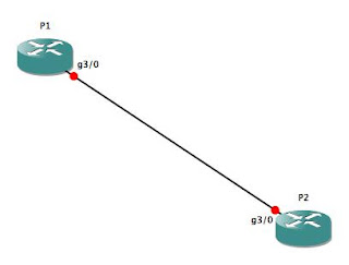
Let's start with the core. Since I am mocking this lab up in GNS3 on a laptop with only 4GB of RAM, the core is going to be very simple: just two routers (P1 and P2), with a single Gig-E connection between them:


As I mentioned in the previous MPLS lab, we must be running CEF in order to run MPLS, so before anything else, make sure you've enabled CEF on the two core routers. Then, we'll put IP addresses on Gig3/0 on both P1 and P2, and configure a Loopback IP address, as well:

P1(config)#ip cef
P1(config)#int lo0
P1(config-if)#ip addr 10.254.254.1 255.255.255.255
P1(config-if)#no shut
P1(config-if)#int gig3/0
P1(config-if)#ip addr 10.0.0.1 255.255.255.252
P1(config-if)#no shut
P1(config-if)#

From this, I'm sure you can figure out how to configure P2 (basically, find any IP address that ends in ".1" and replace it with ".2"), so I won't belabor the point with a full config for P2 here.

Next, we will need to enable MPLS on Gig3/0 on both routers, and turn up OSPF so that our core and provider edge routers can route to each other:

P1(config-if)#int gig3/0
P1(config-if)#mpls ip
P1(config-if)#router ospf 42
P1(config-router)#router-id 10.254.254.1
P1(config-router)#network 10.0.0.0 0.0.0.3 area 0.0.0.0
P1(config-router)#redist conn sub
P1(config-router)#exit
P1(config)#

Once you've made the equivalent changes on P2, you should see the following output on both routers:

*Dec 16 11:40:01.311: %OSPF-5-ADJCHG: Process 42, Nbr 10.254.254.2 on GigabitEthernet3/0 from LOADING to FULL, Loading Done
P1(config)#
*Dec 16 11:40:10.767: %LDP-5-NBRCHG: LDP Neighbor 10.254.254.2:0 (1) is UP
P1(config)#

With that, your P (core) routers are essentially done. You will need to turn up interfaces to connect to your PE (edge) routers -- don't forget the "mpls ip" command on those interfaces! -- and you'll need to establish routing between the P and PE routers, but that should be old hat by now.

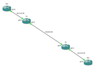
Let's move on to the PE routers. We will connect PE1 to P1, and PE2 to P2, like so...:


...using the following configs:
PE1:
PE1(config)#ip cef
PE1(config)#router ospf 42
PE1(config-router)#router-id 10.254.254.3
PE1(config-router)#int lo0
PE1(config-if)#ip addr 10.254.254.3 255.255.255.255
PE1(config-if)#no shut
PE1(config-if)#ip ospf 42 area 0.0.0.0
PE1(config-if)#int gig2/0
PE1(config-if)#mpls ip
PE1(config-if)#ip addr 10.1.1.2 255.255.255.252
PE1(config-if)#no shut
PE1(config-if)#ip ospf 42 area 0.0.0.0

...and...:

PE2:
PE2(config)#ip cef
PE2(config)#router ospf 42
PE2(config-router)#router-id 10.254.254.4
PE2(config-router)#int lo0
PE2(config-if)#ip addr 10.254.254.4 255.255.255.255
PE2(config-if)#ip ospf 42 area 0.0.0.0
PE2(config-if)#no shut
PE2(config-if)#int gig2/0
PE2(config-if)#mpls ip
PE2(config-if)#ip addr 10.2.1.2 255.255.255.252
PE2(config-if)#ip ospf 42 area 0.0.0.0
PE2(config-if)#no shut

Once you've gotten this far, you should see output similar to this as the various adjacencies come up:

*Dec 16 11:58:31.063: %OSPF-5-ADJCHG: Process 42, Nbr 10.254.254.2 on GigabitEthernet2/0 from LOADING to FULL, Loading Done
*Dec 16 11:58:41.499: %LDP-5-NBRCHG: LDP Neighbor 10.254.254.2:0 (1) is UP

Let's check our routing tables and LDP database to make sure everything is working as expected:

PE1#sho ip route
Codes: C - connected, S - static, R - RIP, M - mobile, B - BGP
       D - EIGRP, EX - EIGRP external, O - OSPF, IA - OSPF inter area
       N1 - OSPF NSSA external type 1, N2 - OSPF NSSA external type 2
       E1 - OSPF external type 1, E2 - OSPF external type 2
       i - IS-IS, su - IS-IS summary, L1 - IS-IS level-1, L2 - IS-IS level-2
       ia - IS-IS inter area, * - candidate default, U - per-user static route
       o - ODR, P - periodic downloaded static route

Gateway of last resort is not set

     10.0.0.0/8 is variably subnetted, 7 subnets, 2 masks
O E2    10.254.254.2/32 [110/20] via 10.1.1.1, 00:10:26, GigabitEthernet2/0
C       10.254.254.3/32 is directly connected, Loopback0
O       10.2.1.0/30 [110/3] via 10.1.1.1, 00:10:26, GigabitEthernet2/0
C       10.1.1.0/30 is directly connected, GigabitEthernet2/0
O       10.0.0.0/30 [110/2] via 10.1.1.1, 00:10:26, GigabitEthernet2/0
O E2    10.254.254.1/32 [110/20] via 10.1.1.1, 00:10:26, GigabitEthernet2/0
O       10.254.254.4/32 [110/4] via 10.1.1.1, 00:05:29, GigabitEthernet2/0
PE1#sho mpls ldp neigh
    Peer LDP Ident: 10.254.254.1:0; Local LDP Ident 10.254.254.3:0
    TCP connection: 10.254.254.1.646 - 10.254.254.3.53411
    State: Oper; Msgs sent/rcvd: 22/21; Downstream
    Up time: 00:10:33
    LDP discovery sources:
      GigabitEthernet2/0, Src IP addr: 10.1.1.1
        Addresses bound to peer LDP Ident:
          10.0.0.1        10.254.254.1    10.1.1.1        
PE1#sho mpls ldp bindings
  lib entry: 10.0.0.0/30, rev 8
    local binding:  label: 17
    remote binding: lsr: 10.254.254.1:0, label: imp-null
  lib entry: 10.1.1.0/30, rev 4
    local binding:  label: imp-null
    remote binding: lsr: 10.254.254.1:0, label: imp-null
  lib entry: 10.2.1.0/30, rev 6
    local binding:  label: 16
    remote binding: lsr: 10.254.254.1:0, label: 17
  lib entry: 10.254.254.1/32, rev 12
    local binding:  label: 19
    remote binding: lsr: 10.254.254.1:0, label: imp-null
  lib entry: 10.254.254.2/32, rev 10
    local binding:  label: 18
    remote binding: lsr: 10.254.254.1:0, label: 16
  lib entry: 10.254.254.3/32, rev 2
    local binding:  label: imp-null
    remote binding: lsr: 10.254.254.1:0, label: 18
  lib entry: 10.254.254.4/32, rev 14
    local binding:  label: 20
    remote binding: lsr: 10.254.254.1:0, label: 19
PE1#

With this, you now have a fully-functional "service provider" MPLS network. Your core is up, your PE routers are up, they are all sharing routes, and they have created LDP bindings between the routers. Sweet! All we need now are some customers to connect to our network so that the provider edge routers can start earning their keep ;)

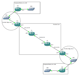
This is where things start to get fun. Suppose the CIO for Perpetual Motion, Inc., an alternative energy provider, approaches you for connectivity across your network. You will turn up an interface for Perpetual Motion on both PE1 and PE2, and create a VRF to isolate Perpetual Motion's network instance from both your own network, as well as from any future customers' networks. Your network now looks like this...:


...with the following config changes on PE1 and PE2:
PE1:
PE1(config)#ip vrf PERPETUAL
PE1(config-vrf)#rd 65000:20
PE1(config-vrf)#route-target both 65000:20
PE1(config-vrf)#int fa0/0
PE1(config-if)#no ip addr
PE1(config-if)#no shut
PE1(config-if)#int fa0/0.20
PE1(config-subif)#encap dot1q 20
PE1(config-subif)#ip vrf forwarding PERPETUAL
PE1(config-subif)#ip addr 100.64.20.1 255.255.255.252
PE1(config-subif)#no shut

PE2:
PE2(config)#ip vrf PERPETUAL
PE2(config-vrf)#rd 65000:20
PE2(config-vrf)#route-target both 65000:20
PE2(config-vrf)#int fa0/0
PE2(config-if)#no ip addr
PE2(config-if)#no shut
PE2(config-if)#int fa0/0.20
PE2(config-subif)#encap dot1q 20
PE2(config-subif)#ip vrf forwarding PERPETUAL
PE2(config-subif)#ip addr 100.64.20.5 255.255.255.252
PE2(config-subif)#no shut

It isn't necessary to turn up a dot-1q encapsulated sub-interface here. We just as easily could turn up a new physical interface for every customer...until we ran out of physical interfaces. Since this is a lab in GNS3, it's not very likely that we would, in fact, run out of physical interfaces (unless you are far more ambitious than I, in which case, you do you!). However, this is pretty much how we provided service to customers at one of my former places of employment, given that SW1 and SW2 could be either actual Ethernet switches or some other kind of Metro-Ethernet network extender (Actelis, Accedian, AdTran, Cisco ME-3400, etc.) or combination thereof. Once the customer configures their routers, we should have point-to-point connectivity between CE1 and PE1, and between CE2 and PE2:

CE1:
CE1#sho run
interface Loopback0
ip address 192.168.254.1 255.255.255.255
ip ospf 1138 area 0.0.0.0
!
interface FastEthernet0/0
ip address 192.168.1.1 255.255.255.0
ip ospf 1138 area 0.0.0.0
!
interface FastEthernet1/1
ip address 100.64.20.2 255.255.255.252
ip ospf network point-to-point
ip ospf 1138 area 0.0.0.0
!
router ospf 1138
router-id 192.168.254.1
log-adjacency-changes
passive-interface FastEthernet0/0
passive-interface Loopback0
!
^c CE1#ping 100.64.20.1
Sending 5, 100-byte ICMP Echos to 100.64.20.1, timeout is 2 seconds:
.!!!!
Success rate is 80 percent (4/5), round-trip min/avg/max = 20/24/32 ms
CE1#

All that is left now is to set up routing between CE1 and CE2. On PE1 and PE2, we will set up an instance of OSPF to accept routes from CE1 and CE2, respectively:

PE1(config-subif)#router ospf 20 vrf PERPETUAL
PE1(config-router)#router-id 100.64.20.1
PE1(config-router)#network 100.64.20.0 0.0.0.3 area 0.0.0.0
PE1(config-subif)#
*Dec 16 14:09:43.579: %OSPF-5-ADJCHG: Process 20, Nbr 192.168.254.1 on FastEthernet0/0.20 from LOADING to FULL, Loading Done
PE1(config-subif)#

CE1(config-if)#router ospf 1138
CE1(config-router)#router-id 100.64.20.2
CE1(config-router)#network 100.64.20.0 0.0.0.3 area 0.0.0.0
CE1(config-router)#int lo0
CE1(config-if)#ip ospf 1138 area 0.0.0.0
CE1(config-if)#int fa0/0
CE1(config-if)#ip ospf 1138 area 0.0.0.0

Now, does it work?

PE1#sho ip route vrf PERPETUAL
...
Gateway of last resort is not set

     100.0.0.0/30 is subnetted, 1 subnets
C       100.64.20.0 is directly connected, FastEthernet0/0.20
     192.168.254.0/32 is subnetted, 1 subnets
O       192.168.254.1 [110/2] via 100.64.20.2, 00:01:40, FastEthernet0/0.20
O    192.168.1.0/24 [110/2] via 100.64.20.2, 00:01:30, FastEthernet0/0.20
PE1#

Looks good! We've got the loopback and Fa0/0 IP addresses in our routing table, so as you can see, all we need to do to set up a customer routing instance on our PE routers is to append "vrf <VRF NAME> to the end of the "router ospf..." statements.

The last step is to set up a multiprotocol BGP process between PE1 and PE2 so that they can share the customer routes between them, then configure redistribution to the OSPF process in the customer VRF. If that sounds complicated, don't worry; it's really not terribly difficult:

PE1:
PE1(config)#router bgp 65000
PE1(config-router)#no synch
PE1(config-router)#neighbor 10.254.254.4 remote-as 65000
PE1(config-router)#neighbor 10.254.254.4 update-source Loopback0
PE1(config-router)#address-family vpnv4
PE1(config-router-af)#neighbor 10.254.254.4 activate
PE1(config-router-af)#neighbor 10.254.254.4 send-community extended
PE1(config-router-af)#exit
PE1(config-router)#address-family ipv4 vrf PERPETUAL
PE1(config-router-af)#redist ospf 20 vrf PERPETUAL
PE1(config-router-af)#no synch
PE1(config-router-af)#exit
PE1(config-router)#exit
PE1(config)#router ospf 20 vrf PERPETUAL
PE1(config-router)#redist bgp 65000 subnets

PE2:
PE2(config)#router bgp 65000
PE2(config-router)#no sync
PE2(config-router)#neighbor 10.254.254.3 remote-as 65000
PE2(config-router)#neighbor 10.254.254.3 update-source Loopback0
PE2(config-router)#address-family vpnv4
PE2(config-router-af)#neighbor 10.254.254.3 activate
PE2(config-router-af)#neighbor 10.254.254.3 send-community extended
PE2(config-router-af)#exit
PE2(config-router)#address-family ipv4 vrf PERPETUAL
PE2(config-router-af)#redist ospf 20 vrf PERPETUAL
PE2(config-router-af)#no sync
PE2(config-router-af)#exit
PE2(config-router)#exit
PE2(config)#router ospf 20 vrf PERPETUAL
PE2(config-router)#redist bgp 65000 sub
PE2(config-router)#exit


Let's check our CE routers and see if they are propagating routes correctly:

CE1#sho ip route
Gateway of last resort is not set

     100.0.0.0/30 is subnetted, 2 subnets
C       100.64.20.0 is directly connected, FastEthernet1/1
O IA    100.64.20.4 [110/2] via 100.64.20.1, 00:02:43, FastEthernet1/1
     192.168.254.0/32 is subnetted, 2 subnets
O IA    192.168.254.2 [110/3] via 100.64.20.1, 00:02:43, FastEthernet1/1
C       192.168.254.1 is directly connected, Loopback0
C    192.168.1.0/24 is directly connected, FastEthernet0/0
O IA 192.168.2.0/24 [110/3] via 100.64.20.1, 00:02:43, FastEthernet1/1
CE1#

CE2:
CE2#sho ip route
Gateway of last resort is not set

     100.0.0.0/30 is subnetted, 2 subnets
O IA    100.64.20.0 [110/2] via 100.64.20.5, 00:02:27, FastEthernet1/1
C       100.64.20.4 is directly connected, FastEthernet1/1
     192.168.254.0/32 is subnetted, 2 subnets
C       192.168.254.2 is directly connected, Loopback0
O IA    192.168.254.1 [110/3] via 100.64.20.5, 00:02:27, FastEthernet1/1
O IA 192.168.1.0/24 [110/3] via 100.64.20.5, 00:02:27, FastEthernet1/1
C    192.168.2.0/24 is directly connected, FastEthernet0/0
CE2#

Yep, on CE1, I can see the Loopback and Fa0/0 IP addresses from CE2, and vice versa. It looks like MPLS is working properly, and like our routing processes are sharing routes in the proper VRF's.

By configuring the P, then PE and CE routers one at a time, it should be fairly obvious how each class of router differs from the others (at least, from a configuration standpoint). The CE routers are the simplest of all, in that they are completely agnostic about the underlying architecture of the service provider network. All they need to do is set up routing, either with a dynamic routing protocol like OSPF or via static routes, with the provider; no special configuration is required on the CE routers at all. Next, in order of complexity, are the P routers. The only additional configuration they require is the "mpls ip" statement in any interface that will be part of the MPLS core. Most of the magic happens in the PE routers, which is reflected in the relative complexity of the PE routers' configs. This is where we create the VRFs, set the route distinguisher and route targets, configure the VRF-aware routing protocols, and set up BGP to redistribute the routes across the core.