Showing posts with label CCNP. Show all posts

Sunday, January 8, 2017

Advanced Cisco Routing -- BGP and OSPF Part 2

Quite a while ago, I created a post on using BGP and OSPF together on Cisco routers. In that particular example, I used OSPF to route within an internal area and BGP to peer with another provider's area, then redistributed OSPF into BGP and BGP into OSPF. If you'll recall, one of the reasons I gave for using BGP when service providers peer with each other is that the Internet's routing tables are too large to incorporate into an interior gateway protocol like OSPF.

This raises a question, however. How can you redistribute BGP into OSPF if OSPF isn't capable of handling that many routes?

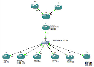
In this lab, I'll show one way of addressing this problem. We'll start by creating the following network:


Warning: I am using publicly routable addresses in this lab! DO NOT try to build this lab on real hardware that is connected to an actual Internet connection, as the potential exists to conflict with real IP addresses actually in use, or to propagate bogus routes into your network!

In this lab, the routers R1 through R6, the routers below the switch in the diagram, are all maintained by various other service providers, and therefore all exist in separate Autonomous Systems (AS's). Meanwhile, the routers above the switch, that is, R7 through R10, are under your control. Because I'm lazy (I've mentioned that before, haven't I?), I simply used loopback interfaces on R1 through R6 to simulate various networks in use on each of the AS's 65512 through 65517. Here is the relevant portions of the config from one of these routers:

interface Loopback0
ip address 141.5.17.1 255.255.255.192
!
interface Loopback1
ip address 141.5.17.65 255.255.255.192
!
interface Loopback2
ip address 141.5.17.129 255.255.255.192
!
interface FastEthernet0/0
ip address 7.7.7.2 255.255.255.240
duplex auto
speed auto
!
router bgp 65513
no synchronization
bgp router-id 141.5.17.1
bgp log-neighbor-changes
network 7.7.7.0 mask 255.255.255.240
network 141.5.17.0 mask 255.255.255.192
network 141.5.17.64 mask 255.255.255.192
network 141.5.17.128 mask 255.255.255.192
neighbor 7.7.7.1 remote-as 65512
neighbor 7.7.7.3 remote-as 65514
neighbor 7.7.7.4 remote-as 65515
neighbor 7.7.7.5 remote-as 65516
neighbor 7.7.7.6 remote-as 65517
neighbor 7.7.7.7 remote-as 65518
no auto-summary
!

One thing I didn't mention in my earlier posts on BGP: the "network" statement in BGP does not operate like the "network" statement in IGP's like OSPF or EIGRP. In this case, the network statement tells BGP what networks you wish to advertise; in an IGP, they enable the routing protocol on the interface that is attached to that network. Consequently, this router (R2, as it happens) is advertising three /26 networks: 141.5.17.0/26, 141.5.17.64/26 and 141.5.17.128/26. It is also offering to peer with six neighbor routers, 7.7.7.1, 7.7.7.3, 7.7.7.4, 7.7.7.5, 7.7.7.6 and 7.7.7.7. So far, pretty straightforward, right?

Likewise, R9 and R10 are pretty straightforward, as well. R8, R9 and R10 are all participating in OSPF area 0.0.0.0:
interface Loopback0
ip address 10.254.254.10 255.255.255.255
!
interface FastEthernet0/0
ip address 194.0.0.10 255.255.255.0
duplex auto
speed auto
!
router ospf 42
router-id 10.254.254.10
log-adjacency-changes
redistribute connected subnets
network 194.0.0.0 0.0.0.255 area 0.0.0.0
!

Again, no surprises here. OSPF is enabled on Fa0/0, and we are redistributing the IP address of our Loopback0 interface in OSPF.

The magic in this lab happens between R7 and R8. In fact, at first glance, you might be wondering why we even put two separate routers here. Since the MTBF of a system of devices decreases with every (non-redundant) device you add to the system (because the probability of a failure of the system is equal to the product of the probability of failure of every non-redundant device in the system), putting two routers in series at this point has decreased the reliability of the network.

The reason for using two routers becomes apparent, however, when you look at the configs:

R7:
interface Loopback0
ip address 10.254.254.7 255.255.255.255
!
interface FastEthernet0/0
ip address 7.7.7.7 255.255.255.240
duplex auto
speed auto
!
interface FastEthernet1/0
ip address 209.112.170.7 255.255.255.0
duplex auto
speed auto
!
router bgp 65518
bgp router-id 10.254.254.7
bgp log-neighbor-changes
neighbor 7.7.7.1 remote-as 65512
neighbor 7.7.7.2 remote-as 65513
neighbor 7.7.7.3 remote-as 65514
neighbor 7.7.7.4 remote-as 65515
neighbor 7.7.7.5 remote-as 65516
neighbor 7.7.7.6 remote-as 65517
neighbor 209.112.170.8 remote-as 65518
!
address-family ipv4
neighbor 7.7.7.1 activate
neighbor 7.7.7.2 activate
neighbor 7.7.7.3 activate
neighbor 7.7.7.4 activate
neighbor 7.7.7.5 activate
neighbor 7.7.7.6 activate
neighbor 209.112.170.8 activate
no auto-summary
no synchronization
network 7.7.7.0 mask 255.255.255.240
network 209.112.170.0
exit-address-family
!

R8:
interface Loopback0
ip address 10.254.254.8 255.255.255.255
!
interface FastEthernet0/0
ip address 209.112.170.8 255.255.255.0
duplex auto
speed auto
!
interface FastEthernet1/0
ip address 194.0.0.8 255.255.255.0
duplex auto
speed auto
!
interface FastEthernet2/0
ip address 193.0.0.8 255.255.255.0
duplex auto
speed auto
!
router ospf 42
router-id 10.254.254.8
log-adjacency-changes
passive-interface Loopback0
network 193.0.0.0 0.0.0.255 area 0.0.0.0
network 194.0.0.0 0.0.0.255 area 0.0.0.0
default-information originate always
!
router bgp 65518
bgp router-id 10.254.254.8
bgp log-neighbor-changes
neighbor 209.112.170.7 remote-as 65518
!
address-family ipv4
neighbor 209.112.170.7 activate
no auto-summary
no synchronization
network 193.0.0.0
network 194.0.0.0
network 209.112.170.0
exit-address-family
!
ip route 0.0.0.0 0.0.0.0 209.112.170.7
!

I don't want to redistribute BGP into OSPF, since that would make the OSPF routing tables too large (okay, not in this example, but if you are peering with actual service providers...). However, I can't just point static routes at the peers either, since that would entirely defeat the purpose of using dynamic routing protocols. Consequently, on R8, I am redistributing OSPF into BGP, then pointing a single default route to R7 and redistributing that default route to R9 and R10 with the "default-information originate" directive on R8. Then, R7 and R8 are BGP peering so that R7 picks up all of the routes in use by R8, R9 and R10 (this is a use of BGP, which is typically an Exterior Gateway Protocol, as an IGP). Because R7 is BGP peering with R1 through R6, it knows how to reach each of the subnets advertised by its peers, and consequently, all of our routers can pass traffic back and forth to each other.
Thursday, October 27, 2016

IPv6 Intro: BGP, OSPF and IPv6...or Maybe Just EIGRP and IPv6, smh

Being a network engineer is kind of like being Sisyphus. Just when you think you you're starting to get to the top of your game, someone moves the target on you. In fact, a writer by the name of Spencer Johnson (M.D.) wrote a book on that subject not quite 20 years ago, and even though I've never read the book, I'd guess that it's at least as relevant today as it was then. Case in point, even though I've used IPv4, OSPF, and EIGRP professionally for years, I don't have a lot of professional experience with IPv6 or BGP. To address that problem, I set up the following network in GNS3 for playing with IPv4 and IPv6 with multiple routing protocols on emulated Cisco 7200 routers:

We have R1, R2 and R3 as routers within an autonomous system, R4 a random (IPv4-only) Internet router and R5 as another (IPv6-only, this time) random Internet router. My intent was to set up BGP peering between R1, R4 and R5, and to have R1, R2 and R3 share routes via OSPF. Sounds easy enough, right?

Hahaha...no.

In a previous lab, we set up OSPFv3 (OSPF for IPv6) on Cisco 3640 routers, so I used those instruction to (try to) set up OSPFv3 on the 7200 routers:
R1(config)#int gig0/0
R1(config-if)#ipv6 ospf 42 area 0.0.0.0
                   ^
% Invalid input detected at '^' marker.

R1(config-if)#ipv6 o?
% Unrecognized command
R1(config-if)#ipv6 ?
IPv6 interface subcommands:
  address             Configure IPv6 address on interface
  authentication      authentication subcommands
...
  multicast           multicast
  nat                 Enable IPv6 NAT on interface
  nd                  IPv6 interface Neighbor Discovery subcommands
  next-hop-self       Configures IP-EIGRP next-hop-self
  policy              Enable IPv6 policy routing
  redirects           Enable sending of ICMP Redirect messages
  rip                 Configure RIP routing protocol
...

Okay...is OSPFv3 not supported on this router? As it turns out, I think it actually is, but I'll save that for another lab.

Edit: no, it's not. I mean, it is, but it isn't. The "hooks" are there to configure OSPFv3 using "ipv6 ospf <process ID>" in global configuration, but you have to have an Advanced IP Services image to run it. The SP Services image I am running isn't licensed for it, because after all, what service provider would run OSPF on their network (answer: every one I've ever worked at), grrr...

For now, I decided to try to set up EIGRP for IPv6 since, 1) it *is* supported on the 7200, and 2) it did not seem to be supported on the 3640's:
R1(config)#int gig0/0
R1(config-if)#ipv6 router eigrp 10
R1(config-rtr)#int gig1/0
R1(config-if)#ipv6 router eigrp 10
R1(config-rtr)#exit
R1(config)#exit
R1#sho run int gig0/0
Building configuration...

Current configuration : 201 bytes
!
interface GigabitEthernet0/0
ip address 66.223.227.5 255.255.255.252
duplex full
speed 1000
media-type gbic
negotiation auto
ipv6 address 2001:C0:FFEE:2::1/126
ipv6 enable
ipv6 eigrp 10
end
R1#sho ipv6 route
IPv6 Routing Table - Default - 8 entries
Codes: C - Connected, L - Local, S - Static, U - Per-user Static route
       M - MIPv6, R - RIP, I1 - ISIS L1, I2 - ISIS L2
       IA - ISIS interarea, IS - ISIS summary, D - EIGRP, EX - EIGRP external
C   2001:C0:FFEE::/126 [0/0]
     via GigabitEthernet1/0, directly connected
L   2001:C0:FFEE::1/128 [0/0]
     via GigabitEthernet1/0, receive
C   2001:C0:FFEE:2::/126 [0/0]
     via GigabitEthernet0/0, directly connected
L   2001:C0:FFEE:2::1/128 [0/0]
     via GigabitEthernet0/0, receive
LC  2001:C0:FFEE:254::1/128 [0/0]
     via Loopback0, receive
C   2016:FA:1::/64 [0/0]
     via FastEthernet6/0.20, directly connected
L   2016:FA:1::1/128 [0/0]
     via FastEthernet6/0.20, receive
L   FF00::/8 [0/0]
     via Null0, receive
R1#

Weird...why are none of my EIGRP routes showing up? I could ping across the interfaces and my IPv4 routing protocols were working as expected, but I could not get EIGRP in IPv6 to form neighbor adjacencies. What gives?

I started troubleshooting EIGRP using essentially the same toolkit I would use for IPv4...:
R1#sho ipv6 eigrp 10 neigh
IPv6-EIGRP neighbors for process 10
% EIGRP 10 is in SHUTDOWN
R1#sho ipv6 eigrp 10 int
IPv6-EIGRP interfaces for process 10
% EIGRP 10 is in SHUTDOWN
R1#

"EIGRP...is in SHUTDOWN?" I'm not familiar with that error message. WWGS ("What Would Google Say")? I quickly found a couple of tutorials on-line which showed that setting up EIGRP in IPv6 on a 7200 is a little different than setting OSPFv3 on a 3640 (go figure). Whereas OSPFv3 on a 3640 is entirely configured on the interface, EIGRP for IPv6 is a mix of interface-level commands and global config commands:
R1#conf t
Enter configuration commands, one per line. End with CNTL/Z.
R1(config)#ipv6 router eigrp 10
R1(config-rtr)#router-id 10.254.254.1
R1(config-rtr)#redistribute connected
R1(config-rtr)#passive-int default
R1(config-rtr)#no passive-int gig0/0
R1(config-rtr)#no passive-int gig1/0
R1(config-rtr)#no shut
02:35:27: %DUAL-5-NBRCHANGE: IPv6-EIGRP(0) 10: Neighbor FE80::C802:7FF:FE00:70 (GigabitEthernet1/0) is up: new adjacency
R1(config-rtr)#
02:35:38: %DUAL-5-NBRCHANGE: IPv6-EIGRP(0) 10: Neighbor FE80::C801:6FF:FEF0:70 (GigabitEthernet0/0) is up: new adjacency
R1(config-rtr)#exit
R1(config)#exit

After making eseentially the same changes on R2 and R3 (the interface names were different, but...), I saw my routes as expected:
R1#sho ipv6 route
IPv6 Routing Table - Default - 12 entries
Codes: C - Connected, L - Local, S - Static, U - Per-user Static route
       M - MIPv6, R - RIP, I1 - ISIS L1, I2 - ISIS L2
       IA - ISIS interarea, IS - ISIS summary, D - EIGRP, EX - EIGRP external
C   2001:C0:FFEE::/126 [0/0]
     via GigabitEthernet1/0, directly connected
L   2001:C0:FFEE::1/128 [0/0]
     via GigabitEthernet1/0, receive
C   2001:C0:FFEE:2::/126 [0/0]
     via GigabitEthernet0/0, directly connected
L   2001:C0:FFEE:2::1/128 [0/0]
     via GigabitEthernet0/0, receive
D   2001:C0:FFEE:3::/64 [90/28416]
     via FE80::C802:7FF:FE00:70, GigabitEthernet1/0
LC  2001:C0:FFEE:254::1/128 [0/0]
     via Loopback0, receive
D   2001:C0:FFEE:254::2/128 [90/130816]
     via FE80::C801:6FF:FEF0:70, GigabitEthernet0/0
D   2001:C0:FFEE:254::3/128 [90/130816]
     via FE80::C802:7FF:FE00:70, GigabitEthernet1/0
D   2001:C0:FFEE:2222::/64 [90/28416]
     via FE80::C801:6FF:FEF0:70, GigabitEthernet0/0
C   2016:FA:1::/64 [0/0]
     via FastEthernet6/0.20, directly connected
L   2016:FA:1::1/128 [0/0]
     via FastEthernet6/0.20, receive
L   FF00::/8 [0/0]
     via Null0, receive
R1#

Well that was more cumbersome than it should have been, but <shrug>. At least we've got EIGRP working now. BGP via IPv4 is nothing new, so I won't waste a lot of time discussing the BGP configuration for R1-R4. However, the IPv6 configuration between R1 and R5 had me swearing at Cisco:
R1(config)#router bgp 65511
R1(config-router)# neighbor 2016:FA:1::5 remote-as 65515
R1(config-router)# address-family ipv6
R1(config-router-af)#  network 2001:C0:FFEE:254:0:0:0:1/128
R1(config-router-af)#  network 2001:C0:FFEE:254:0:0:0:2/128
R1(config-router-af)#  network 2001:C0:FFEE:254:0:0:0:3/128
R1(config-router-af)#  network 2001:C0:FFEE:2:0:0:0:0/126
R1(config-router-af)#  network 2001:C0:FFEE:0:0:0:0:0/126
R1(config-router-af)#  network 2001:C0:FFEE:2222:0:0:0:0/64
R1(config-router-af)#  network 2001:C0:FFEE:3:0:0:0:0/64
R1(config-router-af)#  neighbor 2016:FA:1::5 activate
% BGP context not been initialized properly.
R1(config-router-af)# exit
R1(config-router)#exit
R1(config)#exit
R1#sho bgp ipv6 unicast neighbors

R1#sho run | begin router bgp
router bgp 65511
bgp router-id 10.254.254.1
bgp log-neighbor-changes
neighbor 2016:FA:1::5 remote-as 65515
neighbor 209.193.4.4 remote-as 65514
!
address-family ipv4
  neighbor 209.193.4.4 activate
  no auto-summary
  no synchronization
  network 10.254.254.1 mask 255.255.255.255
  network 10.254.254.2 mask 255.255.255.255
  network 10.254.254.3 mask 255.255.255.255
  network 66.223.224.0 mask 255.255.255.224
  network 66.223.224.32 mask 255.255.255.224
  network 66.223.227.0 mask 255.255.255.252
  network 66.223.227.4 mask 255.255.255.252
  network 209.193.4.0
exit-address-family
!
ip forward-protocol nd
...

Wait, where's my "address-family ipv6" entries, and what's with that "BGP context has not been initialized properly" error message? I went back to the Great Oracle of Google, where I found this little tidbit of information:
Q. Error message: "% BGP context not been initialized properly." when Configuring neighbor under address-family IPv6

A. The issue is with the feature set. If the feature set is SP services, the following services are not supported.

  • IPv6 Routing: Multiprotocol BGP Extensions for IPv6
  • IPv6 Routing: Multiprotocol BGP Link-local Address Peering

To use these features,change the feature set to Advanced Enterprise Services.

Okay, let's check the code version on my routers:
R1#sho ver
Cisco IOS Software, 7200 Software (C7200-SPSERVICESK9-M), Version 12.4(24)T4, RELEASE SOFTWARE (fc2)

Well, <expletive deleted>! Since I don't have an Advanced IP Services image laying around, that pretty much kills the BGP portion of this lab for now.

I went ahead and removed the BGP portion and played with EIGRP across the network, but I'm slightly miffed by the fact that I couldn't do any testing with BGP or OSPF under IPv6, since IPv6 is now a part of certification testing. With adoption of IPv6 "in the wild" still lagging, it would be nice to be able to mock such networks up in a lab without spending a fortune in hardware and software licensing.

Sunday, October 23, 2016

Lesson 16: VRRP

In the last lesson that I wrote while working on my CCNA certification, I introduced the concept of router redundancy via a Cisco proprietary protocol known as HSRP, or "Hot Standby Router Protocol." However, HSRP is not the only way to create a redundant data connection for your office. In this lab, we'll look at a second, similar protocol known as VRRP, or "Virtual Router Redundancy Protocol."

Disclaimer:
The configuration document I used to play with VRRP in this lab didn't work exactly as advertised on the routers I was emulating. In fairness, Cisco 3640 routers are decidedly, ummmm, "old-school" (read that: obsolete), so it's entirely possible that the syntax has changed on more modern platforms that are running more recent versions of IOS. However, what I present here should be close enough to get you started. Here (pdf) is the link to the Cisco document with the slightly different syntax.

As usual, we'll start with the network diagram:


We'll set up lo0 and fa1/0 on R1 and R2 as normal, R4 exists only to act as a DHCP server, and R3 serves as a destination network provider. We'll establish OSPF between R1, R2 and R3, using network statements for 100.64.1.0/30 and 100.64.2.0/30 and using "redistribute connected subnets." On our client, "Knoppix Clone 1," we'll set the default gateway to 100.64.0.1/29. So far, nothing unexpected, right?

Just to recap, the problem we want to solve is, what happens when fa0/0 goes down on our default gateway? If R2 did not exist in this network, then R1 is our single point of failure. If we lose R1, then the clients on our LAN can no longer reach the servers hanging off of R3. To address this, we set up two routers in parallel so that we have a redundant path to R3. However, there is no way to tell a client PC (or router or...) to use multiple default gateways. HSRP and VRRP were designed to address this problem. In both scenarios, you configure a single default gateway on your client network, then use either HSRP or VRRP to shuffle that default gateway address between multiple routers. To set it up, you...:

  1. Enter configuration mode;
  2. Switch to the interface facing your client LAN;
  3. Add an IP address within the subnet of your client LAN;
  4. Configure a meaningful description of the VRRP group;
  5. Configure the client's default gateway address in the VRRP group;
  6. Set the VRRP priority for the router (a higher value takes priority over a lower value);
  7. Set the VRRP advertisement and preempt delay timers.


Here's how the configuration looks on R1...:
interface FastEthernet0/0
ip address 100.64.0.2 255.255.255.248
vrrp 10 description VRRP Group
vrrp 10 ip 100.64.0.1
vrrp 10 preempt delay minimum 3
vrrp 10 priority 254
end

...and on R2:
interface FastEthernet0/0
ip address 100.64.0.3 255.255.255.248
vrrp 10 description VRRP Group
vrrp 10 ip 100.64.0.1
vrrp 10 preempt delay minimum 3
vrrp 10 priority 128
end


NOTE:
I also added the following line to the config...:
R1(config-if)#vrrp 10 timers advertise 1

...to set VRRP to send an "advertisement" every second. However, this is the default behaviour for VRRP, and therefore, it didn't show up in the config until I changed it for testing. Anyway, does it work?

Let's traceroute from R4 to R3:
R4#traceroute 10.254.254.3

Type escape sequence to abort.
Tracing the route to 10.254.254.3

  1 100.64.0.2 4 msec 4 msec 4 msec
  2 100.64.1.2 12 msec 8 msec 8 msec
R4#

Now, if I shut down fa0/0 on R1, I should see a short interruption in service, followed by R2 picking up the traffic:
R4#ping 10.254.254.3 repeat 100

Type escape sequence to abort.
Sending 100, 100-byte ICMP Echos to 10.254.254.3, timeout is 2 seconds:
!!!!!!!!!!!!!..!.!!!!!!!!!!!!!!!!!!!!!!!!!!!!!!!!!!!!!!!!!!!!!!!!!!!!!
!!!!!!!!!!!!!!!!!!!!!!!!!!!!!!
Success rate is 97 percent (97/100), round-trip min/avg/max = 4/11/36 ms
R4#traceroute 10.254.254.3

Type escape sequence to abort.
Tracing the route to 10.254.254.3

1 100.64.0.3 8 msec 4 msec 8 msec
2 100.64.2.2 8 msec 12 msec 8 msec
R4#

Notice how the first hop originally was 100.64.0.2, but now it's 100.64.0.3? VRRP has failed over the virtual 100.64.0.1 IP address from R1 to R2, which is reflected in the traceroute output.

With a little effort, we can see what's happening at the Ethernet level, too, and it's even more interesting. We'll start by verifying our configuration. R1 is currently the VRRP master (i.e., it's hosting the IP address 100.64.0.1), and R2 is the backup:
R1#sho vrrp brief
Interface          Grp Pri Time  Own Pre State   Master addr     Group addr
Fa0/0              10  254 3007       Y  Master  100.64.0.2      100.64.0.1    
R1#
----------------------------------------------------------------------------

R2#sho vrrp brief
Interface          Grp Pri Time  Own Pre State   Master addr     Group addr
Fa0/0              10  128 3500       Y  Backup  100.64.0.2      100.64.0.1    
R2#

First, we'll clear the arp table on Knoppix Client 1:

Now, we'll ping 10.254.254.3 (lo0 on R3) from Knoppix Clone 1:

Next, we shut down fa0/0 on R1, and verify that R2 is now the VRRP master:
R1#sho vrrp brief
Interface          Grp Pri Time  Own Pre State   Master addr     Group addr
Fa0/0              10  254 3007       Y  Init    0.0.0.0         100.64.0.1    
R1#

----------------------------------------------------------------------------

R2#sho vrrp brief
Interface          Grp Pri Time  Own Pre State   Master addr     Group addr
Fa0/0              10  128 3500       Y  Master  100.64.0.3      100.64.0.1    
R2#

...and ping R3 again:

Hmmm...since the VRRP virtual MAC address moves with the router, that doesn't give us much insight into what was actually happening here. Fortunately, I was running tcpdump to capture the Ethernet frames while running this test. After exporting the PCAP file to Wireshark, we can get a little better understanding of what happened here.

Note:
To keep the Wireshark screen captures relevant, I filtered out some of the chatter. We configured VRRP to send advertisements every second, for example, so I filtered out the VRRP protocol data. These routers were also running CDP, so I filtered that as well.

At the very beginning of the capture, we can see Knoppix Client 1 ("CadmusCo_d3:7c:8f") send an arp request for 100.64.0.1, and we can see R1 (cc:00:2a:af:00:00) send an arp reply, stating that the VRRP virtual MAC address "00:00:5e:00:01:0a" is associated with 100.64.0.1:

Then, we ping R3 through R1. As you can see, we sent the ICMP request to the VRRP virtual MAC...:

...but received the reply from the MAC of fa0/0 on R1 (cc:00:2a:af:00:00):

At this point, we shut down fa0/0 on R1, and allowed R2 to take ownership of 100.64.0.1. Since VRRP also transports the virtual MAC, our next ping will still be sent to 00:00:5e:00:01:0a...:

...but this time, our reply has come from the MAC address of fa0/0 on R2 (cc:01:2a:af:00:00):

Because the MAC address doesn't change, we don't have to wait until the arp cache on connected devices times out for traffic to use the new path. This can be a serious problem, in some cases. For example, if you are using a Cisco ASA to connect to a (non-VRRP) "highly-available" system, the default arp cache timeout period is FOUR HOURS, which means it can take up to four hours for your "highly-available" (cough) system to recover from a failover! This isn't just an academic, theoretical point, either. I am currently working a trouble ticket in my day job where this is exactly what's happening. Unfortunately, just shortening the arp cache timeout period can drive up CPU load and memory requirements on busy devices, so there is a balancing act to be found between automatic fail-over times and system resource utilization. VRRP neatly solves that problem by sidestepping the whole issue.

Wednesday, October 5, 2016

IPv6 Intro: Routing with OSPFv3 for IPv6

Continuing on with our last lab, let's remove the RIPng config, and set up OSPFv3, instead. Here's the network diagram again, just so you don't have to jump back to the RIPng lab again:


Just like configuring RIPng, we will start by enabling IPv6 OSPF in the interface configurations. Once again, only R1 is shown, but the other routers are configured in exactly the same way:
R1(config)#int fa0/0
R1(config-if)#ipv6 ospf 42 area 0.0.0.0
R1(config-if)#int s0/0
R1(config-if)#ipv6 ospf 42 area 0.0.0.1
R1(config-if)#exit
R1(config)#do sho ipv6 route
IPv6 Routing Table - 8 entries
Codes: C - Connected, L - Local, S - Static, R - RIP, B - BGP
       U - Per-user Static route
       I1 - ISIS L1, I2 - ISIS L2, IA - ISIS interarea
       O - OSPF intra, OI - OSPF inter, OE1 - OSPF ext 1, OE2 - OSPF ext 2
LC  2001:C0:FFEE::1/128 [0/0]
     via ::, Loopback0
C   2001:C0:FFEE::1:0/125 [0/0]
     via ::, FastEthernet0/0
L   2001:C0:FFEE::1:1/128 [0/0]
     via ::, FastEthernet0/0
C   2001:C0:FFEE::1111:0/126 [0/0]
     via ::, Serial0/0
L   2001:C0:FFEE::1111:1/128 [0/0]
     via ::, Serial0/0
OI  2001:C0:FFEE::2222:0/126 [110/65]
     via FE80::CA03:3CFF:FEAE:0, FastEthernet0/0
L   FE80::/10 [0/0]
     via ::, Null0
L   FF00::/8 [0/0]
     via ::, Null0
R1(config)#

If this looks very familiar from the RIPng lab, it should. Any guesses on how to configure redistribution of connected networks?
R1(config)#ipv6 router ospf 42
R1(config-rtr)#router-id 10.254.254.1
R1(config-rtr)#redist conn
R1(config-rtr)#exit
R1(config)#

At this point, you might be scratching your head, wondering WHY I used an IPv4 address for the router ID. Actually...I didn't. The RFC for OSPF specifies that the router ID is a 32-bit, unique (at least within the AS) identifier. Since IPv4 addresses are ALSO 32-bit, unique identifiers, convention (and, unless a different router ID is specified in the config, Cisco's default behaviour) has set the loopback interface's IPv4 address as the router ID. I also chose to set an IPv4 address on the loopback interface, and I used it as the router ID in this lab. However, technically the OSPFv3 router ID is any random 32-bit number (see the footnote at the end of this lab for more).

After setting up redistribution, the routing table on R1 looks a little more populated:
R1(config)#do sho ipv6 route
IPv6 Routing Table - 12 entries
Codes: C - Connected, L - Local, S - Static, R - RIP, B - BGP
       U - Per-user Static route
       I1 - ISIS L1, I2 - ISIS L2, IA - ISIS interarea
       O - OSPF intra, OI - OSPF inter, OE1 - OSPF ext 1, OE2 - OSPF ext 2
LC  2001:C0:FFEE::1/128 [0/0]
     via ::, Loopback0
OE2  2001:C0:FFEE::2/128 [110/20]
     via FE80::CA03:3CFF:FEAE:0, FastEthernet0/0
OE2  2001:C0:FFEE::3/128 [110/20]
     via FE80::CA04:3CFF:FEAE:0, FastEthernet0/0
OE2  2001:C0:FFEE::4/128 [110/20]
     via FE80::CA00:3CFF:FEAE:0, Serial0/0
OE2  2001:C0:FFEE::5/128 [110/20]
     via FE80::CA03:3CFF:FEAE:0, FastEthernet0/0
C   2001:C0:FFEE::1:0/125 [0/0]
     via ::, FastEthernet0/0
L   2001:C0:FFEE::1:1/128 [0/0]
     via ::, FastEthernet0/0
C   2001:C0:FFEE::1111:0/126 [0/0]
     via ::, Serial0/0
L   2001:C0:FFEE::1111:1/128 [0/0]
     via ::, Serial0/0
OI  2001:C0:FFEE::2222:0/126 [110/65]
     via FE80::CA03:3CFF:FEAE:0, FastEthernet0/0
L   FE80::/10 [0/0]
     via ::, Null0
L   FF00::/8 [0/0]
     via ::, Null0
R1(config)#

There you go: we have a basic OSPFv3 (IPv6) configuration, sharing routes between each of the five routers in our network. We even set up three separate areas: the backbone, consisting of R1, R2 and R3; Area 1, consisting of R1 and R4; and Area 2, consisting of R2 and R5.

Footnote:
At this point, you may be wondering -- well, I am, anyway -- what OSPFv3 uses for a router ID if there are no IPv4 interfaces in use on the router, and there is no router ID specified in the OSPFv3 config. Let's find out, shall we?
R1(config)#int lo0
R1(config-if)#no ip addr
R1(config-if)#shut
R1(config-if)#no shut
R1(config-if)#no ipv6 router ospf 42
R1(config)#int fa0/0
R1(config-if)#ipv6 ospf 42 area 0.0.0.0
R1(config-if)#int s0/0
R1(config-if)#ipv6 ospf 42 area 0.0.0.1
R1(config-if)#exit
R1(config-if)#ipv6 router ospf 42
R1(config-rtr)# redistribute connected
R1(config-rtr)#exit
R1(config)#exit
R1#
00:36:49: %OSPFv3-4-NORTRID: OSPFv3 process 42 could not pick a router-id,
please configure manually
R1#sho ipv6 ospf neigh
%OSPFv3: Router process 42 is not running, please configure a router-id
R1#

Well, that's interesting! What happens if you don't have an IPv4 address on the loopback interface, but you have an IPv4 address on another interface?
R1(config-if)#int vlan 10
R1(config-if)#ip addr 10.254.254.1 255.255.255.252
R1(config-if)#no shut
R1(config-if)#no ipv6 router ospf 42
R1(config)#ipv6 router ospf 42
R1(config-rtr)#redist conn
R1(config-rtr)#exit
R1(config)#int fa0/0
R1(config-if)#ipv6 ospf 42 area 0.0.0.0
R1(config-if)#int s0/0
R1(config-if)#ipv6 ospf 42 area 0.0.0.1
R1(config-if)#exit
R1(config)#exit
R1#sho ipv6 ospf 42 neigh

Neighbor ID    Pri  State      Dead Time  Interface ID  Interface
10.254.254.2     1  FULL/BDR   00:00:39   4             FastEthernet0/0
10.254.254.3     1  FULL/DR    00:00:36   4             FastEthernet0/0
10.254.254.4     1  FULL/  -   00:00:38   5             Serial0/0
R1#

There you have it. If there is an IPv4 address configured anywhere on the router, OSPFv3 will use it for the router ID. If not, then you MUST configure a router ID in the OSPFv3 configuration.

IPv6 Intro: Routing with RIP for IPv6 (RIPng)

In our last lab, we set up a small network with IPv6 and static routes. Let's up the ante a little bit this time, and set up slightly larger network using IPv6 and RIPng.

True Confession: I wanted to start with EIGRP for IPv6, but it isn't supported on either of the routers I have available in GNS3, grrr... However, RIPng is, so we'll go with RIPng for now. I now return you to your regularly scheduled blog post...

Here's the network I am using for this lab:


We start by enabling unicast routing on the routers, and assigning the IPv6 addresses to all of the interfaces (R1 shown, others similar):
R1(config)#ipv6 unicast-routing
R1(config)#int lo0
R1(config-if)#ip addr 10.254.254.1 255.255.255.255
R1(config-if)#ipv6 enable
R1(config-if)#ipv6 address 2001:00C0:FFEE:0000:0000:0000:0000:1/128
R1(config-if)#no shut
R1(config-if)#int fa0/0
R1(config-if)#ipv6 enable
R1(config-if)#ipv6 address 2001:00C0:FFEE:0000:0000:0000:0001:0001/125
R1(config-if)#no shut
R1(config-if)#int s/0/0
R1(config-if)#ipv6 enable
R1(config-if)#ipv6 address 2001:00C0:FFEE:0000:0000:0000:1111:0001/126
R1(config-if)#no shut

Once you have assigned IPv6 addresses to the respective interfaces on all of the routers, you should be able to ping across each subnet, but (for example) R5 shouldn't be able to ping R4:
R5(config)#do ping 2001:C0:FFEE::2222:1

Type escape sequence to abort.
Sending 5, 100-byte ICMP Echos to 2001:C0:FFEE::2222:1, timeout is 2 seconds:
!!!!!
Success rate is 100 percent (5/5), round-trip min/avg/max = 1/9/16 ms
R5(config)#do ping 2001:C0:FFEE::1111:2

Type escape sequence to abort.
Sending 5, 100-byte ICMP Echos to 2001:C0:FFEE::1111:2, timeout is 2 seconds:
.....
Success rate is 0 percent (0/5)
R5(config)#

This is not at all unexpected. In IPv4, you wouldn't be able to ping from R5 to R4 either, unless you had static routes in place or a routing protocol to create the routes between routers that are not directly connected. Let's turn up RIPng on all five routers to share routes across this network (again, R1 shown, but the other routers are similar):
R1(config)#int fa0/0
R1(config-if)#ipv6 rip 10 enable
R1(config-if)#int s0/0
R1(config-if)#ipv6 rip 10 enable
R1(config-if)#exit

That's it! No "network" statements -- just edit the interface configuration to tell the router to start the RIPng process on that interface, and the router will begin sending advertisements for connected networks through that interface. Let's look at the routing table on R1:
R1(config)#do sho ipv6 route
IPv6 Routing Table - 8 entries
Codes: C - Connected, L - Local, S - Static, R - RIP, B - BGP
       U - Per-user Static route
       I1 - ISIS L1, I2 - ISIS L2, IA - ISIS interarea
       O - OSPF intra, OI - OSPF inter, OE1 - OSPF ext 1, OE2 - OSPF ext 2
LC  2001:C0:FFEE::1/128 [0/0]
     via ::, Loopback0
C   2001:C0:FFEE::1:0/125 [0/0]
     via ::, FastEthernet0/0
L   2001:C0:FFEE::1:1/128 [0/0]
     via ::, FastEthernet0/0
C   2001:C0:FFEE::1111:0/126 [0/0]
     via ::, Serial0/0
L   2001:C0:FFEE::1111:1/128 [0/0]
     via ::, Serial0/0
R   2001:C0:FFEE::2222:0/126 [120/2]
     via FE80::CA01:33FF:FE30:0, FastEthernet0/0
L   FE80::/10 [0/0]
     via ::, Null0
L   FF00::/8 [0/0]
     via ::, Null0
R1(config)#

Hmmm...notice that the loopback interfaces for R2 through R5 aren't showing up? Let's edit R1 and R2 to see if enabling RIPng on the loopback interfaces resolves that problem:
R1(config)#int lo0
R1(config-if)#ipv6 rip 10 enable
R1(config-if)#exit
...
R2(config)#int lo0
R2(config-if)#ipv6 rip 10 enable
R2(config-if)#exit

Does R1 see the loopback address on R2 now?
R1(config)#do sho ipv6 route | inc 2001:C0:FFEE::2/128
R 2001:C0:FFEE::2/128 [120/2]
R1(config)#

Yep, that works...but is there a better way to enable RIPng on an interface that isn't actually connected to another host? Let's try something on R3:
R3(config)#ipv6 router rip 10
R3(config-rtr)#redist connected

Does R1 see R3's loopback now?
R1(config)#do sho ipv6 route | inc 2001:C0:FFEE::3/128
R 2001:C0:FFEE::3/128 [120/2]
R1(config)#

Success! On the downside, it's a little hokey that you enable RIPng on the interface, but have to enable redistribution of connected routes in a global configuration, but I suppose that's better than having to enable redistribution on each interface <shrug>

One other thing to look at: let's look at one other thing in the routing table on R1:
R1(config)#do sho ipv6 route
IPv6 Routing Table - 8 entries
<...snip...>
L   FF00::/8 [0/0]
     via ::, Null0
R1(config)#

Once again, there is an odd-looking IPv6 address showing up in the routing table. Let's check our interfaces for anything similar:
R1(config)#do sho ipv6 int brie | inc FF00
R1(config)#

No...nothing there. What gives?

As it turns out, FF02::9 is a multicast address reserved by IANA for RIPng route updates, as defined in RFC 2080. And with that interesting (?) little tidbit of information, we will wrap up this lab on IPv6 routing with RIPng. Next time, we'll dive into OSPFv3.

Tuesday, October 4, 2016

Cisco Routing Oddities -- Interaction Between EIGRP, Distribute-List, and Static Routes

I ran into something at work today that I didn't quite understand, and which I finally had to mock up in GNS-3 to figure out. While trying to track down a routing problem, I found a distribute-list statement on an EIGRP configuration that referenced an access list which denied anything from 10.0.0.0/8. That's not terribly unusual, except that it looked like there were still a lot of 10-dot subnets being propagated by EIGRP on this router. Digging into the configuration a bit more, I saw that there was a "redistribute static" command inside the EIGRP configuration, and I found several static routes to 10-dot subnets. To understand the interaction between EIGRP, static routes, and the "distribute-list" statement, I created the following, simple network in GNS-3:


In this network, R1, R3, R4 and R5 will all use EIGRP to share routes with each other. R2 will have a default route pointing to R1, and R1 will have a single static route to R2's loopback address:
R1(config)#ip route 10.254.254.0 255.255.255.0 10.0.0.2
R1(config)#router eigrp 10
R1(config-router)#redistribute static metric 1000000 1 255 1 1500

After turning up EIGRP, R1 shared all of its known routes with R3, R4 and R5, exactly as you would expect:
R2#ping 100.64.254.1
Sending 5, 100-byte ICMP Echos to 100.64.254.1, timeout is 2 seconds:
!!!!!
Success rate is 100 percent (5/5), round-trip min/avg/max = 4/6/8 ms
R2#

-----------------------------------------------------------------------

R3#ping 10.0.0.2
Sending 5, 100-byte ICMP Echos to 10.0.0.2, timeout is 2 seconds:
!!!!!
Success rate is 100 percent (5/5), round-trip min/avg/max = 8/17/44 ms
R3#

-----------------------------------------------------------------------

R4#ping 10.0.0.2
Sending 5, 100-byte ICMP Echos to 10.0.0.2, timeout is 2 seconds:
!!!!!
Success rate is 100 percent (5/5), round-trip min/avg/max = 12/29/72 ms
R4#

-----------------------------------------------------------------------

R5#ping 10.0.0.2
Sending 5, 100-byte ICMP Echos to 10.0.0.2, timeout is 2 seconds:
!!!!!
Success rate is 100 percent (5/5), round-trip min/avg/max = 12/27/44 ms
R5#

Then, I added the following configuration statements to R1:
R1(config)#ip access-list standard FILTER-NULL-ROUTES
R1(config-std-nacl)#deny 10.0.0.0
R1(config-std-nacl)#permit any
R1(config-std-nacl)#!
R1(config-std-nacl)#router eigrp 10
R1(config-router)#distribute-list FILTER-NULL-ROUTES out
R1(config-router)#!

Running the exact same ping tests...:
R2#ping 100.64.254.1
Sending 5, 100-byte ICMP Echos to 100.64.254.1, timeout is 2 seconds:
!!!!!
Success rate is 100 percent (5/5), round-trip min/avg/max = 4/12/40 ms
R2#

-----------------------------------------------------------------------

R3#ping 10.0.0.2
Sending 5, 100-byte ICMP Echos to 10.0.0.2, timeout is 2 seconds:
.....
Success rate is 0 percent (0/5)
R3#

-----------------------------------------------------------------------

R4#ping 10.0.0.2
Sending 5, 100-byte ICMP Echos to 10.0.0.2, timeout is 2 seconds:
.....
Success rate is 0 percent (0/5)
R4#

-----------------------------------------------------------------------

R5#ping 10.0.0.2
Sending 5, 100-byte ICMP Echos to 10.0.0.2, timeout is 2 seconds:
.....
Success rate is 0 percent (0/5)
R5#

This is to be expected -- 10.0.0.0/30 is a control to verify that the distribute-list is working as expected (that is, that it is filtering 10.0.0.0/8 from the EIGRP updates). Let's see if the distribute-list overrides the static route, or if the static route overrides the distribute-list:
R3#ping 10.254.254.9
Sending 5, 100-byte ICMP Echos to 10.254.254.9, timeout is 2 seconds:
!!!!!
Success rate is 100 percent (5/5), round-trip min/avg/max = 12/23/40 ms
R3#

-----------------------------------------------------------------------

R4#ping 10.254.254.9
Sending 5, 100-byte ICMP Echos to 10.254.254.9, timeout is 2 seconds:
!!!!!
Success rate is 100 percent (5/5), round-trip min/avg/max = 8/35/72 ms
R4#

-----------------------------------------------------------------------

R5#ping 10.254.254.9
Sending 5, 100-byte ICMP Echos to 10.254.254.9, timeout is 2 seconds:
!!!!!
Success rate is 100 percent (5/5), round-trip min/avg/max = 16/28/48 ms
R5#

Notice how we can still reach 10.254.254.9, even though we can no longer reach 10.0.0.2? The distribute-list is filtering 10.0.0.0/8 addresses from the EIGRP routing updates sent by R1. However, we have explicitly stated that we want static routes to be redistributed by EIGRP, and we have a static route for 10.254.254.0/24 via 10.0.0.2. Consequently, R1 is still advertising a route for 10.254.254.9, despite the distribute-list filter. This explains how my router at work was still sharing 10-dot routes with other routers in its EIGRP area, even though there was a distribute-list statement filtering 10-dot subnets.

Monday, September 26, 2016

IPv6 Intro: Global Unicast Address, Link-Local Addresses, and a Brief Intro to Static Routing

In the last lab, we configured a link between R1 and R2, using the IP addresses "2001:co:ffee::4:1" and "2001:co:ffee::4:2," respectively.  Let's try something:
R1#sho ipv6 interface brief
FastEthernet0/0            [up/up]
    FE80::CE00:6BFF:FE8E:0
    2001:C0:FFEE::4:1
Loopback0                  [up/up]
    unassigned
R1#

Well, that's odd! I don't know about you, but I only recall configuring a single IPv6 address on Fa0/0 on R1, but the "sho ipv6 interface brief" command is displaying two addresses.

Actually, it's not odd at all. When you enable IPv6 on an interface, it automatically configures a special class of IPv6 addresses on the interface. Notice how the extra address begins with "FE80?" An IPv6 address that begins with FE80 is a "link-local" address, and they are automatically configured on every interface using IPv6. The IPv6 address that we manually added to the routers is called a "global unicast" address. At this point, you are probably wondering why we bothered to assign an IPv6 address to the interface if the router would automatically assign one, too. There's a hint buried within the names of these address types: "Link-local" and "global-unicast." "Link-local" addresses are locally scoped (where "locally" means local to that one interface), whereas "global-unicast" addresses are, well, globally-scoped. Try to ping the link-local address on R1 from R2:
R2#ping ipv6 fe80:0:0:0:ce00:6bff:fe8e:0
Output Interface: FastEthernet0/0
Type escape sequence to abort.
Sending 5, 100-byte ICMP Echos to FE80::CE00:6BFF:FE8E:0, timeout is 2 seconds:
Packet sent with a source address of FE80::CE01:6BFF:FE8E:0
!!!!!
Success rate is 100 percent (5/5), round-trip min/avg/max = 4/16/36 ms
R2#

Interesting...notice how the router prompted you to specify an output interface? Since link-local addresses are locally-scoped to one specific interface, you have to specify which interface the ping command should use to reach the destination address. Just for giggles, let's add a new interface, Fa1/0, to R2, and connect a third router to that interface:


We'll add the new IPv6 addresses on both R2 and R3 as we've done in the past, and we'll add a static route so that R3 knows how to reach the 2001:co:ffee::4:0/126 network:
R3(config)#ipv6 route 2001:00c0:ffee:0:0:0:4:0/126 2015:0:0:0:0:0:0:1
R3(config)#exit
R3#ping ipv6 2001:00c0:ffee:0:0:0:4:2

Type escape sequence to abort.
Sending 5, 100-byte ICMP Echos to 2001:C0:FFEE::4:2, timeout is 2 seconds:
!!!!!
Success rate is 100 percent (5/5), round-trip min/avg/max = 4/12/36 ms
R3#

Good! Let's add a static route for the link-local address on R2, Fa0/0:
R3(config)#ipv6 route fe80:0000:0000:0000:ce01:6bff:fe8e:0/126 2015:0:0:0:0:0:0:1
% Invalid prefix
R3(config)#

"Locally-scoped" means you can't route these addresses. The only place they are valid is on the interface directly connected to the destination address. Therefore, you can't create a static route for a link-local address. Let's try one more thing, just for the fun of it:


We'll configure the subnet 2001::0/125 on each of these interfaces:
R1(config-if)#int fa0/0
R1(config-if)#ipv6 addr 2001:0:0:0:0:0:0:1/125
R1(config-if)#no shut

R2(config-if)#int fa0/0
R2(config-if)#ipv6 addr 2001:0:0:0:0:0:0:2/125
R2(config-if)#no shut

R3(config-if)#int fa0/0
R3(config-if)#ipv6 addr 2001:0:0:0:0:0:0:3/125
R3(config-if)#no shut

Now, let's make sure each router can ping the other two routers:
R1#ping ipv6 2001:0:0:0:0:0:0:2

Type escape sequence to abort.
Sending 5, 100-byte ICMP Echos to 2001::2, timeout is 2 seconds:
!!!!!
Success rate is 100 percent (5/5), round-trip min/avg/max = 4/12/36 ms
R1#ping ipv6 2001:0:0:0:0:0:0:3

Type escape sequence to abort.
Sending 5, 100-byte ICMP Echos to 2001::3, timeout is 2 seconds:
!!!!!
Success rate is 100 percent (5/5), round-trip min/avg/max = 4/19/36 ms
R1#

(I've omitted the output from R2 and R3 for the sake of brevity, but I did test them)

What about the link-local interfaces? Can we ping them? Let's find out:
R1#sho ipv6 int brie
FastEthernet0/0            [up/up]
    FE80::CE00:6BFF:FE8E:0
    2001::1
<...snip...>
R2#sho ipv6 int brie
FastEthernet0/0            [up/up]
    FE80::CE01:6BFF:FE8E:0
    2001::2
<...snip...>
R3#sho ipv6 int brie
FastEthernet0/0            [up/up]
    FE80::CE03:6BFF:FE8E:0
    2001::3
<...snip...>

Now that we have the link-local addresses on each router, we'll try the ping test:
R1#ping ipv6 FE80::CE01:6BFF:FE8E:0
Output Interface: FastEthernet0/0
Type escape sequence to abort.
Sending 5, 100-byte ICMP Echos to FE80::CE01:6BFF:FE8E:0, timeout is 2 seconds:
Packet sent with a source address of FE80::CE00:6BFF:FE8E:0
!!!!!
Success rate is 100 percent (5/5), round-trip min/avg/max = 4/22/40 ms
R1#ping ipv6 FE80::CE03:6BFF:FE8E:0
Output Interface: FastEthernet0/0
Type escape sequence to abort.
Sending 5, 100-byte ICMP Echos to FE80::CE03:6BFF:FE8E:0, timeout is 2 seconds:
Packet sent with a source address of FE80::CE00:6BFF:FE8E:0
!!!!!
Success rate is 100 percent (5/5), round-trip min/avg/max = 4/12/36 ms
R1#
<...snip...>

R2#ping ipv6 FE80::CE00:6BFF:FE8E:0
Output Interface: FastEthernet0/0
Type escape sequence to abort.
Sending 5, 100-byte ICMP Echos to FE80::CE00:6BFF:FE8E:0, timeout is 2 seconds:
Packet sent with a source address of FE80::CE01:6BFF:FE8E:0
!!!!!
Success rate is 100 percent (5/5), round-trip min/avg/max = 4/5/8 ms
R2#ping ipv6 FE80::CE03:6BFF:FE8E:0
Output Interface: FastEthernet0/0
Type escape sequence to abort.
Sending 5, 100-byte ICMP Echos to FE80::CE03:6BFF:FE8E:0, timeout is 2 seconds:
Packet sent with a source address of FE80::CE01:6BFF:FE8E:0
!!!!!
Success rate is 100 percent (5/5), round-trip min/avg/max = 4/10/20 ms
R2#
<...snip...>

R3#ping ipv6 FE80::CE00:6BFF:FE8E:0
Output Interface: FastEthernet0/0
Type escape sequence to abort.
Sending 5, 100-byte ICMP Echos to FE80::CE00:6BFF:FE8E:0, timeout is 2 seconds:
Packet sent with a source address of FE80::CE03:6BFF:FE8E:0
!!!!!
Success rate is 100 percent (5/5), round-trip min/avg/max = 4/14/40 ms
R3#ping ipv6 FE80::CE01:6BFF:FE8E:0
Output Interface: FastEthernet0/0
Type escape sequence to abort.
Sending 5, 100-byte ICMP Echos to FE80::CE01:6BFF:FE8E:0, timeout is 2 seconds:
Packet sent with a source address of FE80::CE03:6BFF:FE8E:0
!!!!!
Success rate is 100 percent (5/5), round-trip min/avg/max = 4/15/36 ms
R3#
<...snip...>


As you can see, the link-local interface is not limited to point-to-point networks; it will also work on multipoint networks.

One other interesting point to raise about IPv6 addresses: there is no broadcast address, as there is in IPv4. Instead, IPv6 uses multicast to replicate the functionality of IPv4 broadcast addresses. In additon to global unicast, link-local and multicast addresses, IPv6 also supports a few other special classes of addresses, but we will save them for another day. With what we have covered in this lab and the previous lab, we now have enough grounding to start playing with routing...but I'll save that for the next lab.

IPv6 Intro: Address Format and Subnetting

A couple of years ago, I created a lab, Advanced Cisco Routing: Implementing OSPF in IPv6. I probably got the cart before the horse when I created that lab, since that was the only in this blog (so far) where we even discussed IPv6. Ideally, I should have given an intro to IPv6 addressing and networking before creating a lab where we implemented a routing protocol in IPv6. Today, I'd like to fix that problem. Let's start with a basic introduction to IPv6, from the beginning.

I won't spend a lot of time discussing the need for IPv6. If you are reading this blog, you are already well aware that we network types are quickly running out of free IPv4 addresses, and that in an increasingly connected world, we need to implement a new Layer-3 protocol in order to connect all of our devices to the public Internet. Good enough? ;) Good. Let's proceed with a description of IPv6.

Basic Format of an IPv6 Address:
In IPv4, a valid IP address is a 32-bit number, broken down into four groups of 8-bit numbers -- that is, four groups of digits, each of which can be in the range 0-255. For example, 10.254.254.1 is a valid IP address, as is 172.16.0.4 and 192.168.131.75. Technically, any grouping of octets from 0.0.0.0 to 255.255.255.255 would be valid for IP addressing. However, in practice, parts of the address space have been reserved for special purposes, and therefore, 224.0.0.0 through 255.255.255.255 are not usable for addressing hosts.

Because one of the primary drivers for IPv6 is a lack of IPv4 address space, an IPv6 address is rather more complex. Where IPv4 addresses are 32 bits in length, an IPv6 address is 128 bits in length. Where IPv4 addresses are typically written in decimal notation, IPv6 addresses are written in hexidecimal. Additionally, where an IPv4 address is divided into four groups of 8 bits, separated by a period ("."), IPv6 addresses are subdivided into eight groups of 16-bits each, separated by a colon (":"). For example:
2001:4840:af21:0000:0000:2112:2358:0042
fe80:0000:0000:0000:baca:8ffe:fe42:f138

Because hexidecimal numbers contain alphabetic characters between "A" and "F," you will often see IPv6 addresses with...ummm...clever (?)...words enmbedded in the addresses:
2016:00c0:ffee:4a11:0000:0000:0000:0001
2001:dead:beef:cafe:0000:0000:0000:0128

...which helps with memorizing frequently used addresses. Even better, if an address contains a long sequence of zeroes, you can abbreviate the IPv6 address by replacing the sequence with two colons (":"):
2016:00c0:ffee:4a11::0001

Actually, even that can be shortened, because it isn't necessary to include all of the leading zeroes in each 16-bit string, like so:
2016:c0:ffee:4a11::1

Note: This only applies to LEADING zeroes, however, because trailing zeroes are placeholders, and therefore are required! Consequently, you cannot shorten "2016:c0:ffee:4a11::1" any further, as the zero in "2016" and "c0" must be present. One other catch: you can only truncate sequences of zeroes ONCE in an IPv6 address. For example, if you had the complete IPv6 address, "2001:0000:0042:0000:0000:0000:0000:af41," you would have to choose which sequence of zeroes to truncate. These would be acceptable:
2001::42:0000:0000:0000:0000:af41
2001:0000:42::af41

...but this would not:
2001::42::af41

That is because with either of the first two examples, you can still determine where within the 128 bits of address the "42" lies, but "2001::42::af41" could be any of the following addresses:
2001:0000:0042:0000:0000:0000:0000:af41
2001:0000:0000:0042:0000:0000:0000:af41
2001:0000:0000:0000:0042:0000:0000:af41
2001:0000:0000:0000:0000:0042:0000:af41

Note: Wait a minute! When you abbreviated the full IPv6 address as "2001:0000:42::af41,", you dropped the two leading zeroes ahead of the "42" in "0042," even though you replaced all of the zeroes after "42!"

Yes, but since you can only drop the leading zeroes in a 16-bit segment (i.e., "0042" can be abbreviated as "42," but "4200" cannot), we still know exactly where it belongs in the full, expanded IPv6 address.

Subnetting:
Just as in IPv4, IPv6 addresses can be subnetted. Just as 10.254.254.1/32 is a host address in IPv4, 2001::192:168:1:1/128 is a host address in IPv6. You can subdivide networks in IPv6 to optimize the number of networks and hosts in exactly the same way that you would in IPv4. However, it is important to remember that IPv6 uses hexadecimal numbers, so if you decide to "encapsulate" a common IPv4 address in IPv6 as I did above, don't make the mistake of assuming that, for example, 2001::192:168:1:9/126 and 2001::192.168.1.10/126 are contiguous host addresses within the same subnet. They aren't, as I discovered in a lab recently ;) Between ":9" and ":10" in an IPv6 address, you will find ":a" through ":f" -- which spans two /126 subnets, with ":10" being the network address (as opposed to a host address) for yet another subnet!

Putting it into practice!
Let's create a lab in GNS3 (or actual hardware, if you'd prefer) where we start connecting devices with IPv6. We'll start with a very simple network consisting of two routers. For this first lab, all we'll do is enable IPv6 on the routers, apply an IPv6 address to the connected interfaces, and make sure we can ping across the connection:


Now, we'll turn up the IPv6 addresses on these two routers:
R1(config)#ipv6 unicast-routing
R1(config)#int fa0/0
R1(config-if)#ipv6 enable
R1(config-if)#ipv6 address 2001:00c0:ffee:0000:0000:0000:0004:0001/126
R1(config-if)#no shut
R1(config-if)#exit
R1(config#exit

...and on R2:
R2(config)#ipv6 unicast-routing
R2(config)#int fa0/0
R2(config-if)#ipv6 enable
R2(config-if)#ipv6 address 2001:00c0:ffee:0000:0000:0000:0004:0002/126
R2(config-if)#no shut
R2(config-if)#exit
R2(config#exit

Can we ping?
R1#ping ipv6 2001:00c0:ffee:0000:0000:0000:0004:0002

Type escape sequence to abort.
Sending 5, 100-byte ICMP Echos to 2001:C0:FFEE::4:2, timeout is 2 seconds:
!!!!!
Success rate is 100 percent (5/5), round-trip min/avg/max = 4/19/36 ms
R1#

How about from R2?
R2#ping ipv6 2001:00c0:ffee:0000:0000:0000:0004:0001

Type escape sequence to abort.
Sending 5, 100-byte ICMP Echos to 2001:C0:FFEE::4:1, timeout is 2 seconds:
!!!!!
Success rate is 100 percent (5/5), round-trip min/avg/max = 4/5/12 ms
R2#

Perfect! We have met the objectives of this lab, so we'll call it a day.

IPv6 Intro: Address Format and Subnetting

A couple of years ago, I created a lab, Advanced Cisco Routing: Implementing OSPF in IPv6. I probably got the cart before the horse when I created that lab, since that was the only in this blog (so far) where we even discussed IPv6. Ideally, I should have given an intro to IPv6 addressing and networking before creating a lab where we implemented a routing protocol in IPv6. Today, I'd like to fix that problem. Let's start with a basic introduction to IPv6, from the beginning.

I won't spend a lot of time discussing the need for IPv6. If you are reading this blog, you are already well aware that we network types are quickly running out of free IPv4 addresses, and that in an increasingly connected world, we need to implement a new Layer-3 protocol in order to connect all of our devices to the public Internet. Good enough? ;) Good. Let's proceed with a description of IPv6.

Basic Format of an IPv6 Address:
In IPv4, a valid IP address is a 32-bit number, broken down into four groups of 8-bit numbers -- that is, four groups of digits, each of which can be in the range 0-255. For example, 10.254.254.1 is a valid IP address, as is 172.16.0.4 and 192.168.131.75. Technically, any grouping of octets from 0.0.0.0 to 255.255.255.255 would be valid for IP addressing. However, in practice, parts of the address space have been reserved for special purposes, and therefore, 224.0.0.0 through 255.255.255.255 are not usable for addressing hosts.

Because one of the primary drivers for IPv6 is a lack of IPv4 address space, an IPv6 address is rather more complex. Where IPv4 addresses are 32 bits in length, an IPv6 address is 128 bits in length. Where IPv4 addresses are typically written in decimal notation, IPv6 addresses are written in hexidecimal. Additionally, where an IPv4 address is divided into four groups of 8 bits, separated by a period ("."), IPv6 addresses are subdivided into eight groups of 16-bits each, separated by a colon (":"). For example:
2001:4840:af21:0000:0000:2112:2358:0042
fe80:0000:0000:0000:baca:8ffe:fe42:f138

Because hexidecimal numbers contain alphabetic characters between "A" and "F," you will often see IPv6 addresses with...ummm...clever (?)...words enmbedded in the addresses:
2016:00c0:ffee:4a11:0000:0000:0000:0001
2001:dead:beef:cafe:0000:0000:0000:0128

...which helps with memorizing frequently used addresses. Even better, if an address contains a long sequence of zeroes, you can abbreviate the IPv6 address by replacing the sequence with two colons (":"):
2016:00c0:ffee:4a11::0001

Actually, even that can be shortened, because it isn't necessary to include all of the leading zeroes in each 16-bit string, like so:
2016:c0:ffee:4a11::1

Note: This only applies to LEADING zeroes, however, because trailing zeroes are placeholders, and therefore are required! Consequently, you cannot shorten "2016:c0:ffee:4a11::1" any further, as the zero in "2016" and "c0" must be present. One other catch: you can only truncate sequences of zeroes ONCE in an IPv6 address. For example, if you had the complete IPv6 address, "2001:0000:0042:0000:0000:0000:0000:af41," you would have to choose which sequence of zeroes to truncate. These would be acceptable:
2001::42:0000:0000:0000:0000:af41
2001:0000:42::af41

...but this would not:
2001::42::af41

That is because with either of the first two examples, you can still determine where within the 128 bits of address the "42" lies, but "2001::42::af41" could be any of the following addresses:
2001:0000:0042:0000:0000:0000:0000:af41
2001:0000:0000:0042:0000:0000:0000:af41
2001:0000:0000:0000:0042:0000:0000:af41
2001:0000:0000:0000:0000:0042:0000:af41

Note: Wait a minute! When you abbreviated the full IPv6 address as "2001:0000:42::af41,", you dropped the two leading zeroes ahead of the "42" in "0042," even though you replaced all of the zeroes after "42!"

Yes, but since you can only drop the leading zeroes in a 16-bit segment (i.e., "0042" can be abbreviated as "42," but "4200" cannot), we still know exactly where it belongs in the full, expanded IPv6 address.
Subnetting:
Just as in IPv4, IPv6 addresses can be subnetted. Just as 10.254.254.1/32 is a host address in IPv4, 2001::192:168:1:1/128 is a host address in IPv6. You can subdivide networks in IPv6 to optimize the number of networks and hosts in exactly the same way that you would in IPv4. However, it is important to remember that IPv6 uses hexadecimal numbers, so if you decide to "encapsulate" a common IPv4 address in IPv6 as I did above, don't make the mistake of assuming that, for example, 2001::192:168:1:9/126 and 2001::192.168.1.10/126 are contiguous host addresses within the same subnet. They aren't, as I discovered in a lab recently ;) Between "::9" and "::10" in an IPv6 address, you will find "::a" through "::f" -- which spans two /126 subnets, with "::10" being the network address for a third!

Putting it into practice!
Let's create a lab in GNS3 (or actual hardware, if you'd prefer) where we start connecting devices with IPv6. We'll start with a very simple network consisting of two routers. For this first lab, all we'll do is enable IPv6 on the routers, apply an IPv6 address to the connected interfaces, and make sure we can ping across the connection:


Now, we'll turn up the IPv6 addresses on these two routers:
R1(config)#ipv6 unicast-routing
R1(config)#int fa0/0
R1(config-if)#ipv6 enable
R1(config-if)#ipv6 address 2001:00c0:ffee:0000:0000:0000:0004:0001/126
R1(config-if)#no shut
R1(config-if)#exit
R1(config#exit

...and on R2:
R2(config)#ipv6 unicast-routing
R2(config)#int fa0/0
R2(config-if)#ipv6 enable
R2(config-if)#ipv6 address 2001:00c0:ffee:0000:0000:0000:0004:0002/126
R2(config-if)#no shut
R2(config-if)#exit
R2(config#exit
>
Can we ping?
R1#ping ipv6 2001:00c0:ffee:0000:0000:0000:0004:0002

Type escape sequence to abort.
Sending 5, 100-byte ICMP Echos to 2001:C0:FFEE::4:2, timeout is 2 seconds:
!!!!!
Success rate is 100 percent (5/5), round-trip min/avg/max = 4/19/36 ms
R1#

How about from R2?
R2#ping ipv6 2001:00c0:ffee:0000:0000:0000:0004:0001

Type escape sequence to abort.
Sending 5, 100-byte ICMP Echos to 2001:C0:FFEE::4:1, timeout is 2 seconds:
!!!!!
Success rate is 100 percent (5/5), round-trip min/avg/max = 4/5/12 ms
R2#

Perfect! We have met the objectives of this lab, so we'll call it a day.

Tuesday, September 13, 2016

Cisco Advanced Routing Lab: Redistribution, Default Routes, and Virtual Tunnels

Today, I felt like challenging myself a little bit, so I created a large, somewhat complex network in GNS3 to try putting several concepts together into one, cohesive network. As usual, we'll start with the network diagram:


R1, R2, R3 and R4 are the network core. These routers all live in Area 0 (in the center of the diagram). R1 also participates in Area 1 and shares routes via BGP with R5. R5 participates in an entirely separate OSPF domain with R6 (my idea was that R5 and R6 would be "Internet" hosts for this lab). Just like R1, R2 also participates in Area 1, providing a redundant link to this area. R3 participates in OSPF area 3 and is one of the endpoints for the virtual tunnel to Area 4. R4 also belongs to Area 2. R7, 8 and 9 are pretty straightforward, existing only in Area 1. Likewise, R10 and R11 only live in Area 2; there's nothing complex about their configurations, either. R12, however, is the boundary between Area 2 and the RIP network including R13. R14 and R15 are routers belonging to Area 3, but R16 is a little more tricky. R16 participates in both Area 3 and Area 4.

However, OSPF requires ALL OSPF areas connect to the backbone (area 0) by at least one router. If you notice, there is no direct link between Area 4 and Area 0 in this network diagram, so in order to have Area 4 share routes with the rest of the network, you need to create a "virtual link" between R16 and R3. If ever you find yourself with an OSPF area that doesn't connect to the backbone, it might be worth rethinking your network design so that all of your areas do connect to Area 0. Speaking in broad generalities, there's usually something flawed with your design if you can't connect various OSPF areas directly to the backbone, but if for some reason you can't, it's pretty easy to connect R16 and R3 via a virtual tunnel. First, on R3:
R3(config)#router ospf 42
R3(config-router)#area 0.0.0.3 virtual-link 10.254.254.16


...and on R16:
R16(config)#router ospf 42
R16(config-router)#area 0.0.0.3 virtual-link 10.254.254.3


That's it! There are several options -- such as the various timers -- that you can adjust to account for various network performance issues across the virtual tunnel, but that's essentially all there is to creating the tunnel. Inside the OSPF config on each tunnel endpoint, you list the area ID of the OSPF area that the tunnel will be transiting, and you give the IP address of the other router's OSPF router-ID. In this network, I am using 10.254.254.<router number> for the loopback0 IP address, so R3 is 10.254.254.3 and R16 is 10.254.254.16.

The next "interesting" feature of this lab is the redistribution between OSPF Area 2 and the RIP network on R12. On R13, I created several 172.16.x.y networks on loopback interfaces...:
R13#sho ip int brie
Interface         IP-Address    OK? Method Status...
FastEthernet0/0   unassigned    YES unset  admin...
FastEthernet1/0   10.128.12.2   YES manual up ...
FastEthernet2/0   unassigned    YES unset  admin...
FastEthernet3/0   unassigned    YES unset  admin...
Loopback0         10.254.254.13 YES manual up...
Loopback1         172.16.1.1    YES manual up...
Loopback2         172.16.2.1    YES manual up...
Loopback3         172.17.1.1    YES manual up...
Loopback4         172.17.3.1    YES manual up...

RIPv1 is classful, while we are using classless routing, so the first thing to do is make sure that we are using RIPv2 on both R12 and R13:
R12(config)#router rip
R12(config-router)#version 2

Next, on R12, I want to tell RIP to redistribute OSPF routes, but to add a metric that is sufficiently large that R12 and R13 will prefer local routes to routes that have been imported from OSPF:
R12(config-router)#redistribute ospf 42 metric 3

Since RIP, being a distance-vector protocol, uses hop count as a metric (with a maximum of 15 hops), we start routes imported from OSPF with a hop count of 3 (the "42" is the OSPF process ID I used in the lab -- "router ospf 42"). Now, we'll do the same thing with OSPF:
R12(config-router)#router ospf 42
R12(config-router)#redistribute rip metric 50000 subnets

Again, we are setting the OSPF metric for routes important from RIP to an arbitrarily large value, so that OSPF will prefer local routes to imported routes; the exact value may require some tweaking on your network. I am also using the "subnets" option to tell OSPF to import just the specific subnets that RIP is advertising. Otherwise, any subnets from Class A IP space will be imported as /8 networks; any subnets from Class B IP space will be imported as /16 subnets; and any subnets from Class C IP space will be imported as /24 subnets (in other words, the two 172.16.x.y/24 subnets on R13 would be imported as a single 172.16.0.0/16, the two 172.16.x.y/24 subnets would be imported as a single 172.17.0.0/16, and the 10.254.254.13/32 subnet would be imported as 10.0.0.0/8 -- not at all what we wanted!).

On R1, we are advertising all of the subnets hosted in all of the OSPF areas as well as the RIP network to R5 via BGP:
router bgp 2358
no synchronization
bgp router-id 100.64.0.2
bgp log-neighbor-changes
network 10.0.0.4 mask 255.255.255.252
network 10.0.0.8 mask 255.255.255.252
network 10.0.1.4 mask 255.255.255.252
... network 172.16.0.0
network 172.17.0.0
network 192.168.9.0
neighbor 100.64.0.1 remote-as 2112
no auto-summary
!

It would also be possible to simply import OSPF into BGP, rather than list all of the subnets individually. However, this raises an interesting point: how do you import the routes that R5 is sharing via BGP into the network? The whole point of BGP is to share extremely large routing tables between routers. You don't want to import the entire Internet's routing tables into OSPF, so what is the best way to share external routes with the other routers in your internal network?

In this case, I used a simple, one-line statement to have the other routers send traffic destined for external networks to R1:
R1(config)#router ospf 42
R1(config-router)#default-information originate always
Since R5 is sharing its routes with R1, R1 knows how to reach the external subnets. By adding the "default-information originate" command to R1's OSPF config, it is essentially telling the other routers within the network that is the default gateway -- that traffic destined for unknown networks should be sent to it. R5 has the exact same statement in its OSPF config, so that R6 can reach the networks R5 has received via BGP.

Tuesday, June 7, 2016

BGP Route Filtering

Consider the network in the following diagram...:

If you apply a simple BGP configuration to each router in this network, something along the lines of...:
#R5 BGP Configuration:
router bgp 500
no synchronization
bgp router-id 10.254.254.5
bgp log-neighbor-changes
network 10.254.254.5 mask 255.255.255.255
network 172.16.0.0 mask 255.255.255.252
network 172.16.0.16 mask 255.255.255.252
neighbor 172.16.0.2 remote-as 100
neighbor 172.16.0.17 remote-as 400
no auto-summary

...BGP will find the "best" route around the network. For example, for R1 to ping R4's loopback address, it would take the route R1, R5, R4, and to ping R3's loopback address, R1 would take the route R1, R2, R3:
R1#sho ip route
<---snip--->
10.0.0.0/32 is subnetted, 5 subnets
B 10.254.254.2 [20/0] via 172.16.0.6, 00:00:10
B 10.254.254.3 [20/0] via 172.16.0.6, 00:00:10
C 10.254.254.1 is directly connected, Loopback0
B 10.254.254.4 [20/0] via 172.16.0.1, 00:00:09
B 10.254.254.5 [20/0] via 172.16.0.1, 00:00:15
R1#

Exactly as you would expect, right?

It could happen, however, that there is some factor of which BGP is unaware that makes this routing less than optimal. Suppose, for example, that you are the administrator of router R5, and while you would like to multi-home your router, you don't want to allow other networks to transit your router. To prevent BGP from advertising routes to other networks, it is possible to filter outbound routes from your router.

Step 1: Create an access list to define the networks you want to allow outbound.
R5(config)#access-list 1 permit 10.254.254.5 0.0.0.0
R5(config)#access-list 1 permit 172.16.0.0 0.0.0.3
R5(config)#access-list 1 permit 172.16.0.16 0.0.0.3

Step 2: Edit the BGP config to filter the routes as defined in your access list.
R5(config)#router bgp 500
R5(config-router)# neighbor 172.16.0.2 distribute-list 1 out
R5(config-router)# neighbor 172.16.0.17 distribute-list 1 out

Step 3: Clear the BGP sessions to reset the routes.
R5#clear ip bgp 100
R5#clear ip bgp 400
R5#
00:49:41: %BGP-5-ADJCHANGE: neighbor 172.16.0.2 Down User reset
R5#
00:49:43: %BGP-5-ADJCHANGE: neighbor 172.16.0.17 Down User reset
R5#

Now, if you look at the routes on R1, it will only transit R1 to reach networks that are directly connected to R1:
R1#sho ip route
<---snip--->
172.16.0.0/30 is subnetted, 5 subnets
B 172.16.0.16 [20/0] via 172.16.0.1, 00:01:28
B 172.16.0.12 [20/0] via 172.16.0.6, 00:09:24
B 172.16.0.8 [20/0] via 172.16.0.6, 00:09:24
C 172.16.0.4 is directly connected, FastEthernet0/0
C 172.16.0.0 is directly connected, FastEthernet3/0
10.0.0.0/32 is subnetted, 5 subnets
B 10.254.254.2 [20/0] via 172.16.0.6, 00:09:24
B 10.254.254.3 [20/0] via 172.16.0.6, 00:09:24
C 10.254.254.1 is directly connected, Loopback0
B 10.254.254.4 [20/0] via 172.16.0.6, 00:02:21
B 10.254.254.5 [20/0] via 172.16.0.1, 00:01:28
R1#

As you can see, to reach R4's loopback address now, R1 now will route traffic through R2 rather than through R5.

Now, what would happen if there was a break somewhere in between R2 and R4?
R2#conf t
R2(config)#int fa0/0
R2(config-if)#shut

R1#ping 10.254.254.4

Type escape sequence to abort.
Sending 5, 100-byte ICMP Echos to 10.254.254.4, timeout is 2 seconds:
.....
Success rate is 0 percent (0/5)
R1#

R5 will not propagate any routes except those that you have explicitly allowed, and as a result, R1 no longer has a route to R4.

Friday, August 21, 2015

Cisco BGP Local Preference

As I've mentioned before, I work at a service provider. I recently had a customer come to my employer to ask if we could build a network for them that would allow them to replicate a subnet at two separate locations. When everything was working as expected, they wanted traffic to this subnet to be routed to their main location. However, in the event of a network outage, they wanted traffic to this subnet to be routed to their off-site backup location.

No problem. BGP will allow us to set up weighting on one of the routes so that we can prefer a route from one of the customer's routers, but will revert to the less preferred route if the primary site goes off-line for any reason. To explain how it's done, we'll use this example network:


R1 and R2 are my routers. R3 and R4 are the customer's routers, with R3 being the primary location, and R4 being the secondary site. R5 is $Random_Internet_Host.

We'll start by configuring the IP addresses on each of the routers.

R1:
R1#sho ip int brie
Interface                  IP-Address      OK? Method Status                Protocol
FastEthernet0/0            10.0.0.1        YES manual up                    up
FastEthernet1/0            172.16.3.1      YES manual up                    up
FastEthernet2/0            100.64.17.1   YES manual up                    up
FastEthernet3/0            unassigned      YES unset  administratively down down
Loopback0                  10.254.254.1    YES manual up                    up
R1#

R2:
R2#sho ip int brie
Interface                  IP-Address      OK? Method Status                Protocol
FastEthernet0/0            10.0.0.2        YES manual up                    up
FastEthernet1/0            172.16.4.1      YES manual up                    up
FastEthernet2/0            unassigned      YES unset  administratively down down
FastEthernet3/0            unassigned      YES unset  administratively down down
Loopback0                  10.254.254.2    YES manual up                    up
R2#

R3:
R3#sho ip int brie
Interface                  IP-Address      OK? Method Status                Protocol
FastEthernet0/0            192.168.1.1     YES manual up                    up
FastEthernet1/0            172.16.3.2      YES manual up                    up
FastEthernet2/0            unassigned      YES unset  administratively down down
FastEthernet3/0            unassigned      YES unset  administratively down down
Loopback0                  10.10.10.3      YES manual up                    up
R3#

R4:
R4#sho ip int brie
Interface                  IP-Address      OK? Method Status                Protocol
FastEthernet0/0            192.168.1.1     YES manual up                    up
FastEthernet1/0            172.16.4.2      YES manual up                    up
FastEthernet2/0            unassigned      YES unset  administratively down down
FastEthernet3/0            unassigned      YES unset  administratively down down
Loopback0                  10.10.10.4      YES manual up                    up
R4#

We'll skip R5's IP configuration, since it doesn't really matter for this lab -- any subnet(s) that isn't being used elsewhere is fine on R5.

Next, we'll start with an ordinary BGP configuration on each of the routers:

R1:
router bgp 42
no synchronization
bgp router-id 10.254.254.1
bgp log-neighbor-changes
network 10.0.0.0 mask 255.255.255.0
network 172.16.3.0 mask 255.255.255.252
network 100.64.17.0 mask 255.255.255.0
neighbor 10.0.0.2 remote-as 42
neighbor 172.16.3.2 remote-as 2358
neighbor 100.64.17.5 remote-as 2112
no auto-summary
!

R2:
router bgp 42
no synchronization
bgp router-id 10.254.254.2
bgp log-neighbor-changes
network 10.0.0.0 mask 255.255.255.0
network 172.16.4.0 mask 255.255.255.252
neighbor 10.0.0.1 remote-as 42
neighbor 172.16.4.2 remote-as 2358
no auto-summary
!

R3:
router bgp 2358
no synchronization
bgp router-id 10.10.10.3
bgp log-neighbor-changes
network 10.10.10.3 mask 255.255.255.255
network 172.16.3.0 mask 255.255.255.252
network 192.168.1.0
neighbor 172.16.3.1 remote-as 42
no auto-summary
!

R4:
router bgp 2358
no synchronization
bgp router-id 10.10.10.4
bgp log-neighbor-changes
network 10.10.10.4 mask 255.255.255.255
network 172.16.4.0 mask 255.255.255.252
network 192.168.1.0
neighbor 172.16.4.1 remote-as 42
no auto-summary
!

Again, we'll skip R5, as nothing special is going on there. It's just a straight peering configuration with R1.

Give the routers time to establish BGP adjacencies and to discover all of the routes on this network, then on R1 and R2, run the "show ip route" command:

R1#sho ip route
<...snip...>
     169.254.0.0/24 is subnetted, 1 subnets
B       169.254.1.0 [20/0] via 100.64.17.5, 01:59:05
     172.16.0.0/30 is subnetted, 2 subnets
B       172.16.4.0 [200/0] via 10.0.0.2, 00:37:33
C       172.16.3.0 is directly connected, FastEthernet1/0
     8.0.0.0/32 is subnetted, 1 subnets
B       8.8.8.8 [20/0] via 100.64.17.5, 01:59:05
     10.0.0.0/8 is variably subnetted, 5 subnets, 2 masks
B       10.254.254.2/32 [200/0] via 10.0.0.2, 00:37:33
B       10.10.10.3/32 [20/0] via 172.16.3.2, 00:37:25
C       10.0.0.0/24 is directly connected, FastEthernet0/0
C       10.254.254.1/32 is directly connected, Loopback0
B       10.10.10.4/32 [200/0] via 172.16.4.2, 00:37:14
     12.0.0.0/16 is subnetted, 1 subnets
B       12.12.0.0 [20/0] via 100.64.17.5, 01:59:06
C    100.64.17.0/24 is directly connected, FastEthernet2/0
B    192.168.1.0/24 [20/0] via 172.16.3.2, 00:37:25
R1#

R2#sho ip route
<...snip...>
     169.254.0.0/24 is subnetted, 1 subnets
B       169.254.1.0 [200/0] via 100.64.17.5, 00:37:13
     172.16.0.0/30 is subnetted, 2 subnets
C       172.16.4.0 is directly connected, FastEthernet1/0
B       172.16.3.0 [200/0] via 10.0.0.1, 00:38:13
     8.0.0.0/32 is subnetted, 1 subnets
B       8.8.8.8 [200/0] via 100.64.17.5, 00:37:13
     10.0.0.0/8 is variably subnetted, 4 subnets, 2 masks
C       10.254.254.2/32 is directly connected, Loopback0
B       10.10.10.3/32 [200/0] via 172.16.3.2, 00:38:01
C       10.0.0.0/24 is directly connected, FastEthernet0/0
B       10.10.10.4/32 [20/0] via 172.16.4.2, 00:37:59
     12.0.0.0/16 is subnetted, 1 subnets
B       12.12.0.0 [200/0] via 100.64.17.5, 00:37:14
B    100.64.17.0/24 [200/0] via 10.0.0.1, 00:38:14
B    192.168.1.0/24 [20/0] via 172.16.4.2, 00:37:59
R2#

If you'll notice, R1 has discovered the route to 192.168.1.0/24 via 172.16.3.2 (R3), but R2 has discovered the route to 192.168.1.0/24 via 172.16.4.2 (R4). This is not what we want. We want all traffic routed to R3 until and unless R3 goes off-line; right now, traffic will be routed to either R3 OR R4 based upon whether it passes through R1 or R2. To fix this, we'll create an access list to match the 192.168.1.0/24 subnet, then apply it to a route map, and finally, apply the route map to the BGP configuration on R2:

R2(config)#access-list 5 permit 192.168.1.0 0.0.0.255
R2(config)#route-map LPREF permit 10
R2(config-route-map)#match ip address 5
R2(config-route-map)#set weight 100
R2(config-route-map)#route-map LPREF permit 20
R2(config-route-map)#exit
R2(config)#router bgp 42
R2(config-router)#neighbor 10.0.0.1 route-map LPREF in
R2(config-router)#

At this point, if you run the "sho ip route" command again, you'll notice that nothing has changed. Clear the BGP session with R1 to apply the change to your BGP configuration:

R2#clear ip bgp 42
R2#
02:43:14: %BGP-5-ADJCHANGE: neighbor 10.0.0.1 Down User reset
R2#
02:43:19: %BGP-5-ADJCHANGE: neighbor 10.0.0.1 Up
R2#sho ip route | inc 192.168.1.
B 192.168.1.0/24 [200/0] via 172.16.3.2, 00:00:12
R2#

BGP uses hop count to determine the preferred path when it has multiple routes to a subnet. Since there is one hop to 192.168.1.0/24 via 172.16.4.2, and two hops to 192.168.1.0/24 via 172.16.3.2 (from R2's perspective), R2 will route to R4 by default. What we've done is adjust the weighting for routes from R1 matching "192.168.1.xxx" to 100, so that R2 will prefer the route through R1 and R3 over the route from R4:

R2#sho ip bgp
<...snip...>
   Network          Next Hop            Metric LocPrf Weight Path
<...snip...>
*>i192.168.1.0      172.16.3.2               0    100    100 2358 i
*                   172.16.4.2               0             0 2358 i
<...snip...>
R2#

If you shut fa-1/0 on R3, then wait about four minutes, you'll see both R1 and R2 change their route to 192.168.1.0/24 to traverse R4 rather than R3. This is kind of a long time for an outage, but that delay can be tuned by adjusting the BGP timers. However, adjusting the timers too aggressively can lead to other problems. That means that a proper discussion on tuning BGP timers is probably beyond the scope of this lesson, so I'll save that for another day.