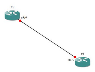
Let's start with the core. Since I am mocking this lab up in GNS3 on a laptop with only 4GB of RAM, the core is going to be very simple: just two routers (P1 and P2), with a single Gig-E connection between them:

As I mentioned in the previous MPLS lab, we must be running CEF in order to run MPLS, so before anything else, make sure you've enabled CEF on the two core routers. Then, we'll put IP addresses on Gig3/0 on both P1 and P2, and configure a Loopback IP address, as well:
P1(config)#ip cef

P1(config)#int lo0

P1(config-if)#ip addr 10.254.254.1 255.255.255.255

P1(config-if)#no shut

P1(config-if)#int gig3/0

P1(config-if)#ip addr 10.0.0.1 255.255.255.252

P1(config-if)#no shut

P1(config-if)#
From this, I'm sure you can figure out how to configure P2 (basically, find any IP address that ends in ".1" and replace it with ".2"), so I won't belabor the point with a full config for P2 here.
Next, we will need to enable MPLS on Gig3/0 on both routers, and turn up OSPF so that our core and provider edge routers can route to each other:
P1(config-if)#int gig3/0

P1(config-if)#mpls ip

P1(config-if)#router ospf 42

P1(config-router)#router-id 10.254.254.1

P1(config-router)#network 10.0.0.0 0.0.0.3 area 0.0.0.0

P1(config-router)#redist conn sub

P1(config-router)#exit

P1(config)#
Once you've made the equivalent changes on P2, you should see the following output on both routers:
*Dec 16 11:40:01.311: %OSPF-5-ADJCHG: Process 42, Nbr 10.254.254.2 on GigabitEthernet3/0 from LOADING to FULL, Loading Done

P1(config)#

*Dec 16 11:40:10.767: %LDP-5-NBRCHG: LDP Neighbor 10.254.254.2:0 (1) is UP

P1(config)#
With that, your P (core) routers are essentially done. You will need to turn up interfaces to connect to your PE (edge) routers -- don't forget the "mpls ip" command on those interfaces! -- and you'll need to establish routing between the P and PE routers, but that should be old hat by now.
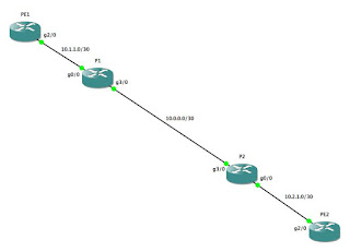
Let's move on to the PE routers. We will connect PE1 to P1, and PE2 to P2, like so...:

...using the following configs:
PE1:
PE1(config)#ip cef

PE1(config)#router ospf 42

PE1(config-router)#router-id 10.254.254.3

PE1(config-router)#int lo0

PE1(config-if)#ip addr 10.254.254.3 255.255.255.255

PE1(config-if)#no shut

PE1(config-if)#ip ospf 42 area 0.0.0.0

PE1(config-if)#int gig2/0

PE1(config-if)#mpls ip

PE1(config-if)#ip addr 10.1.1.2 255.255.255.252

PE1(config-if)#no shut

PE1(config-if)#ip ospf 42 area 0.0.0.0
...and...:
PE2:
PE2(config)#ip cef

PE2(config)#router ospf 42

PE2(config-router)#router-id 10.254.254.4

PE2(config-router)#int lo0

PE2(config-if)#ip addr 10.254.254.4 255.255.255.255

PE2(config-if)#ip ospf 42 area 0.0.0.0

PE2(config-if)#no shut

PE2(config-if)#int gig2/0

PE2(config-if)#mpls ip

PE2(config-if)#ip addr 10.2.1.2 255.255.255.252

PE2(config-if)#ip ospf 42 area 0.0.0.0

PE2(config-if)#no shut
Once you've gotten this far, you should see output similar to this as the various adjacencies come up:
*Dec 16 11:58:31.063: %OSPF-5-ADJCHG: Process 42, Nbr 10.254.254.2 on GigabitEthernet2/0 from LOADING to FULL, Loading Done

*Dec 16 11:58:41.499: %LDP-5-NBRCHG: LDP Neighbor 10.254.254.2:0 (1) is UP
Let's check our routing tables and LDP database to make sure everything is working as expected:
PE1#sho ip route

Codes: C - connected, S - static, R - RIP, M - mobile, B - BGP

       D - EIGRP, EX - EIGRP external, O - OSPF, IA - OSPF inter area

       N1 - OSPF NSSA external type 1, N2 - OSPF NSSA external type 2

       E1 - OSPF external type 1, E2 - OSPF external type 2

       i - IS-IS, su - IS-IS summary, L1 - IS-IS level-1, L2 - IS-IS level-2

       ia - IS-IS inter area, * - candidate default, U - per-user static route

       o - ODR, P - periodic downloaded static route


Gateway of last resort is not set


     10.0.0.0/8 is variably subnetted, 7 subnets, 2 masks

O E2    10.254.254.2/32 [110/20] via 10.1.1.1, 00:10:26, GigabitEthernet2/0

C       10.254.254.3/32 is directly connected, Loopback0

O       10.2.1.0/30 [110/3] via 10.1.1.1, 00:10:26, GigabitEthernet2/0

C       10.1.1.0/30 is directly connected, GigabitEthernet2/0

O       10.0.0.0/30 [110/2] via 10.1.1.1, 00:10:26, GigabitEthernet2/0

O E2    10.254.254.1/32 [110/20] via 10.1.1.1, 00:10:26, GigabitEthernet2/0

O       10.254.254.4/32 [110/4] via 10.1.1.1, 00:05:29, GigabitEthernet2/0

PE1#sho mpls ldp neigh

    Peer LDP Ident: 10.254.254.1:0; Local LDP Ident 10.254.254.3:0

    TCP connection: 10.254.254.1.646 - 10.254.254.3.53411

    State: Oper; Msgs sent/rcvd: 22/21; Downstream

    Up time: 00:10:33

    LDP discovery sources:

      GigabitEthernet2/0, Src IP addr: 10.1.1.1

        Addresses bound to peer LDP Ident:

          10.0.0.1        10.254.254.1    10.1.1.1

PE1#sho mpls ldp bindings

  lib entry: 10.0.0.0/30, rev 8

    local binding:  label: 17

    remote binding: lsr: 10.254.254.1:0, label: imp-null

  lib entry: 10.1.1.0/30, rev 4

    local binding:  label: imp-null

    remote binding: lsr: 10.254.254.1:0, label: imp-null

  lib entry: 10.2.1.0/30, rev 6

    local binding:  label: 16

    remote binding: lsr: 10.254.254.1:0, label: 17

  lib entry: 10.254.254.1/32, rev 12

    local binding:  label: 19

    remote binding: lsr: 10.254.254.1:0, label: imp-null

  lib entry: 10.254.254.2/32, rev 10

    local binding:  label: 18

    remote binding: lsr: 10.254.254.1:0, label: 16

  lib entry: 10.254.254.3/32, rev 2

    local binding:  label: imp-null

    remote binding: lsr: 10.254.254.1:0, label: 18

  lib entry: 10.254.254.4/32, rev 14

    local binding:  label: 20

    remote binding: lsr: 10.254.254.1:0, label: 19

PE1#
With this, you now have a fully-functional "service provider" MPLS network. Your core is up, your PE routers are up, they are all sharing routes, and they have created LDP bindings between the routers. Sweet! All we need now are some customers to connect to our network so that the provider edge routers can start earning their keep ;)
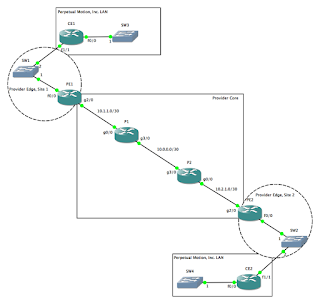
This is where things start to get fun. Suppose the CIO for Perpetual Motion, Inc., an alternative energy provider, approaches you for connectivity across your network. You will turn up an interface for Perpetual Motion on both PE1 and PE2, and create a VRF to isolate Perpetual Motion's network instance from both your own network, as well as from any future customers' networks. Your network now looks like this...:

...with the following config changes on PE1 and PE2:
PE1:
PE1(config)#ip vrf PERPETUAL

PE1(config-vrf)#rd 65000:20

PE1(config-vrf)#route-target both 65000:20

PE1(config-vrf)#int fa0/0

PE1(config-if)#no ip addr

PE1(config-if)#no shut

PE1(config-if)#int fa0/0.20

PE1(config-subif)#encap dot1q 20

PE1(config-subif)#ip vrf forwarding PERPETUAL

PE1(config-subif)#ip addr 100.64.20.1 255.255.255.252

PE1(config-subif)#no shut
PE2:
PE2(config)#ip vrf PERPETUAL

PE2(config-vrf)#rd 65000:20

PE2(config-vrf)#route-target both 65000:20

PE2(config-vrf)#int fa0/0

PE2(config-if)#no ip addr

PE2(config-if)#no shut

PE2(config-if)#int fa0/0.20

PE2(config-subif)#encap dot1q 20

PE2(config-subif)#ip vrf forwarding PERPETUAL

PE2(config-subif)#ip addr 100.64.20.5 255.255.255.252

PE2(config-subif)#no shut
It isn't necessary to turn up a dot-1q encapsulated sub-interface here. We just as easily could turn up a new physical interface for every customer...until we ran out of physical interfaces. Since this is a lab in GNS3, it's not very likely that we would, in fact, run out of physical interfaces (unless you are far more ambitious than I, in which case, you do you!). However, this is pretty much how we provided service to customers at one of my former places of employment, given that SW1 and SW2 could be either actual Ethernet switches or some other kind of Metro-Ethernet network extender (Actelis, Accedian, AdTran, Cisco ME-3400, etc.) or combination thereof. Once the customer configures their routers, we should have point-to-point connectivity between CE1 and PE1, and between CE2 and PE2:
CE1:
CE1#sho run

interface Loopback0

 ip address 192.168.254.1 255.255.255.255

 ip ospf 1138 area 0.0.0.0

!

interface FastEthernet0/0

 ip address 192.168.1.1 255.255.255.0

 ip ospf 1138 area 0.0.0.0

!

interface FastEthernet1/1

 ip address 100.64.20.2 255.255.255.252

 ip ospf network point-to-point

 ip ospf 1138 area 0.0.0.0

!

router ospf 1138

 router-id 192.168.254.1

 log-adjacency-changes

 passive-interface FastEthernet0/0

 passive-interface Loopback0

!

^c
CE1#ping 100.64.20.1

Sending 5, 100-byte ICMP Echos to 100.64.20.1, timeout is 2 seconds:

.!!!!

Success rate is 80 percent (4/5), round-trip min/avg/max = 20/24/32 ms

CE1#
All that is left now is to set up routing between CE1 and CE2. On PE1 and PE2, we will set up an instance of OSPF to accept routes from CE1 and CE2, respectively:
PE1(config-subif)#router ospf 20 vrf PERPETUAL

PE1(config-router)#router-id 100.64.20.1

PE1(config-router)#network 100.64.20.0 0.0.0.3 area 0.0.0.0

PE1(config-subif)#

*Dec 16 14:09:43.579: %OSPF-5-ADJCHG: Process 20, Nbr 192.168.254.1 on FastEthernet0/0.20 from LOADING to FULL, Loading Done

PE1(config-subif)#
CE1(config-if)#router ospf 1138

CE1(config-router)#router-id 100.64.20.2

CE1(config-router)#network 100.64.20.0 0.0.0.3 area 0.0.0.0

CE1(config-router)#int lo0

CE1(config-if)#ip ospf 1138 area 0.0.0.0

CE1(config-if)#int fa0/0

CE1(config-if)#ip ospf 1138 area 0.0.0.0
Now, does it work?
PE1#sho ip route vrf PERPETUAL

...

Gateway of last resort is not set


     100.0.0.0/30 is subnetted, 1 subnets

C       100.64.20.0 is directly connected, FastEthernet0/0.20

     192.168.254.0/32 is subnetted, 1 subnets

O       192.168.254.1 [110/2] via 100.64.20.2, 00:01:40, FastEthernet0/0.20

O    192.168.1.0/24 [110/2] via 100.64.20.2, 00:01:30, FastEthernet0/0.20

PE1#
Looks good! We've got the loopback and Fa0/0 IP addresses in our routing table, so as you can see, all we need to do to set up a customer routing instance on our PE routers is to append "vrf <VRF NAME> to the end of the "router ospf..." statements.
The last step is to set up a multiprotocol BGP process between PE1 and PE2 so that they can share the customer routes between them, then configure redistribution to the OSPF process in the customer VRF. If that sounds complicated, don't worry; it's really not terribly difficult:
PE1:
PE1(config)#router bgp 65000

PE1(config-router)#no synch

PE1(config-router)#neighbor 10.254.254.4 remote-as 65000

PE1(config-router)#neighbor 10.254.254.4 update-source Loopback0

PE1(config-router)#address-family vpnv4

PE1(config-router-af)#neighbor 10.254.254.4 activate

PE1(config-router-af)#neighbor 10.254.254.4 send-community extended

PE1(config-router-af)#exit

PE1(config-router)#address-family ipv4 vrf PERPETUAL

PE1(config-router-af)#redist ospf 20 vrf PERPETUAL

PE1(config-router-af)#no synch

PE1(config-router-af)#exit

PE1(config-router)#exit

PE1(config)#router ospf 20 vrf PERPETUAL

PE1(config-router)#redist bgp 65000 subnets
PE2:
PE2(config)#router bgp 65000

PE2(config-router)#no sync

PE2(config-router)#neighbor 10.254.254.3 remote-as 65000

PE2(config-router)#neighbor 10.254.254.3 update-source Loopback0

PE2(config-router)#address-family vpnv4

PE2(config-router-af)#neighbor 10.254.254.3 activate

PE2(config-router-af)#neighbor 10.254.254.3 send-community extended

PE2(config-router-af)#exit

PE2(config-router)#address-family ipv4 vrf PERPETUAL

PE2(config-router-af)#redist ospf 20 vrf PERPETUAL

PE2(config-router-af)#no sync

PE2(config-router-af)#exit

PE2(config-router)#exit

PE2(config)#router ospf 20 vrf PERPETUAL

PE2(config-router)#redist bgp 65000 sub

PE2(config-router)#exit
Let's check our CE routers and see if they are propagating routes correctly:
CE1#sho ip route

Gateway of last resort is not set


     100.0.0.0/30 is subnetted, 2 subnets

C       100.64.20.0 is directly connected, FastEthernet1/1

O IA    100.64.20.4 [110/2] via 100.64.20.1, 00:02:43, FastEthernet1/1

     192.168.254.0/32 is subnetted, 2 subnets

O IA    192.168.254.2 [110/3] via 100.64.20.1, 00:02:43, FastEthernet1/1

C       192.168.254.1 is directly connected, Loopback0

C    192.168.1.0/24 is directly connected, FastEthernet0/0

O IA 192.168.2.0/24 [110/3] via 100.64.20.1, 00:02:43, FastEthernet1/1

CE1#
CE2:
CE2#sho ip route

Gateway of last resort is not set


     100.0.0.0/30 is subnetted, 2 subnets

O IA    100.64.20.0 [110/2] via 100.64.20.5, 00:02:27, FastEthernet1/1

C       100.64.20.4 is directly connected, FastEthernet1/1

     192.168.254.0/32 is subnetted, 2 subnets

C       192.168.254.2 is directly connected, Loopback0

O IA    192.168.254.1 [110/3] via 100.64.20.5, 00:02:27, FastEthernet1/1

O IA 192.168.1.0/24 [110/3] via 100.64.20.5, 00:02:27, FastEthernet1/1

C    192.168.2.0/24 is directly connected, FastEthernet0/0

CE2#
Yep, on CE1, I can see the Loopback and Fa0/0 IP addresses from CE2, and vice versa. It looks like MPLS is working properly, and like our routing processes are sharing routes in the proper VRF's.
By configuring the P, then PE and CE routers one at a time, it should be fairly obvious how each class of router differs from the others (at least, from a configuration standpoint). The CE routers are the simplest of all, in that they are completely agnostic about the underlying architecture of the service provider network. All they need to do is set up routing, either with a dynamic routing protocol like OSPF or via static routes, with the provider; no special configuration is required on the CE routers at all. Next, in order of complexity, are the P routers. The only additional configuration they require is the "mpls ip" statement in any interface that will be part of the MPLS core. Most of the magic happens in the PE routers, which is reflected in the relative complexity of the PE routers' configs. This is where we create the VRFs, set the route distinguisher and route targets, configure the VRF-aware routing protocols, and set up BGP to redistribute the routes across the core.
No comments:
Post a Comment