Sunday, January 8, 2017

Advanced Cisco Routing -- BGP MED (Multi-Exit Discriminator)

Suppose we have two connections to our upstream ISP: a high-speed link from Cust-A to ISP-1, and a low-speed link from Cust-A to ISP-2 (Cust-B is just a random Internet host):


Here are the subnets in use on this network:

SubnetEndpoint AEndpoint A InterfaceEndpoint BEndpoint B Interface
10.254.254.1ISP-1Lo0N/AN/A
10.254.254.2ISP-2Lo0N/AN/A
100.64.1.254Cust-ALo0N/AN/A
100.64.2.254Cust-ALo0N/AN/A
10.0.0.0/30ISP-1Gig-E 1/0Cust-AGig-E 1/0
10.0.0.4/30ISP-1Gig-E 2/0Cust-BGig-E 1/0
10.0.0.8/30ISP-1Gig-E 3/0ISP-2Gig-E 3/0
10.0.0.12/30ISP-2Gig-E 1/0Cust-BGig-E 2/0
100.64.1.0/26Cust-AFast-E 0/0Knoppix-32Eth 1/0
100.64.2.0/26Cust-BFast-E 0/0CentOS7_1Eth 1/0

Obviously, we would typically want traffic to flow across the high-speed link rather than the low-speed link. However, BGP doesn't consider bandwidth when determining the "best" path from one host to another:


As you can see, BGP has selected a route via the low-speed circuit from the host Knoppix-32 PC to the CentOS7_1 web server in Cust_B's network. To solve this problem, it's easy enough to set a weight on the outbound link to force traffic to use the circuit connected to ISP-1. All we have to do is set a sufficiently high metric on the route we want to take:

Cust-A
router bgp 65512
neighbor 10.0.0.1 weight 30

Since higher weights take priority over lower weights, this will force outbound traffic to use ISP-1 rather than ISP-2. However, that only has an effect on our outbound traffic. BGP may still provide a route from Cust-B back to us through ISP-2 (the low-bandwidth circuit). This potentially causes two problems: first, we'd rather have our traffic go through the faster circuit (for obvious reasons); and second, this can cause "asymmetric routing." Some applications and network devices (stateful firewalls, for example) really don't like asymmetric routing. Unfortunately, trying to troubleshoot a problem caused by asymmetric routing can be a real PITA, and no, not the tasty kind :( To force other networks to prefer the path via ISP-1, we will adjust BGP's "MED" ("Multi Exit Discriminator"), one of the metrics that BGP uses to calculate the "best" route between endpoints. First, on our router, we'll create an access list to identify our internal networks:

Cust-A(config)#ip access-list standard BGP_Internal_Nets
Cust-A(config-std-nacl)#permit 100.64.1.0 0.0.0.63
Cust-A(config-std-nacl)#permit host 100.64.1.254

Next, we create a route map:

Cust-A(config)#route-map BGP_MED 10
Cust-A(config-route-map)#match ip addr BGP_Internal_Nets
Cust-A(config-route-map)#set metric 110

Finally, we apply the route map to the LESS-PREFERRED neighbor (ISP-2) in our BGP configuration:

Cust-A(config)#router bgp 65512
Cust-A(config-router)#neighbor 172.16.0.1 route-map BGP_MED out
Cust-A(config-router)#exit
Cust-A(config)#exit
Cust-A#clear ip bgp 65511

Unlike weight, a lower MED is preferable to a higher MED, and therefore, by advertising a higher-than-default MED to ISP-2's BGP process, we are effectively telling it to prefer an alternate route to our network.

After BGP re-converges, we should see that both ISP-1 and ISP-2 are using the higher-bandwidth link via ISP-1 to reach 100.64.1.x:

ISP-1#sho ip bgp | inc 65512
*  10.0.0.0/30      10.0.0.2                 0             0 65512 i
*> 100.64.1.0/26    10.0.0.2                 0             0 65512 i
*> 100.64.1.254/32  10.0.0.2                 0             0 65512 i
*  172.16.0.0/30    10.0.0.2                 0             0 65512 i
ISP-1#

...and...:

ISP-2(config)#do sho ip bgp | inc 65512
*>i100.64.1.0/26    10.0.0.2                 0    100      0 65512 i
*                   172.16.0.2             110             0 65512 i
*>i100.64.1.254/32  10.0.0.2                 0    100      0 65512 i
*                   172.16.0.2             110             0 65512 i
ISP-2(config)#

Perfect! Both routers are now advertising a preferred route via ISP-1, just as we wanted (">" indicates a preferred route). You can verify this by a traceroute from CentOS7_1:


By setting the MED in our BGP config, we have redundant links to our ISP, but will still prefer the high-bandwidth circuit unless there is a problem. I'll leave testing fail-over as an exercise for the reader ;)
Advanced Cisco Routing -- BGP and OSPF Part 2

Quite a while ago, I created a post on using BGP and OSPF together on Cisco routers. In that particular example, I used OSPF to route within an internal area and BGP to peer with another provider's area, then redistributed OSPF into BGP and BGP into OSPF. If you'll recall, one of the reasons I gave for using BGP when service providers peer with each other is that the Internet's routing tables are too large to incorporate into an interior gateway protocol like OSPF.

This raises a question, however. How can you redistribute BGP into OSPF if OSPF isn't capable of handling that many routes?

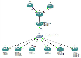
In this lab, I'll show one way of addressing this problem. We'll start by creating the following network:


Warning: I am using publicly routable addresses in this lab! DO NOT try to build this lab on real hardware that is connected to an actual Internet connection, as the potential exists to conflict with real IP addresses actually in use, or to propagate bogus routes into your network!

In this lab, the routers R1 through R6, the routers below the switch in the diagram, are all maintained by various other service providers, and therefore all exist in separate Autonomous Systems (AS's). Meanwhile, the routers above the switch, that is, R7 through R10, are under your control. Because I'm lazy (I've mentioned that before, haven't I?), I simply used loopback interfaces on R1 through R6 to simulate various networks in use on each of the AS's 65512 through 65517. Here is the relevant portions of the config from one of these routers:

interface Loopback0
ip address 141.5.17.1 255.255.255.192
!
interface Loopback1
ip address 141.5.17.65 255.255.255.192
!
interface Loopback2
ip address 141.5.17.129 255.255.255.192
!
interface FastEthernet0/0
ip address 7.7.7.2 255.255.255.240
duplex auto
speed auto
!
router bgp 65513
no synchronization
bgp router-id 141.5.17.1
bgp log-neighbor-changes
network 7.7.7.0 mask 255.255.255.240
network 141.5.17.0 mask 255.255.255.192
network 141.5.17.64 mask 255.255.255.192
network 141.5.17.128 mask 255.255.255.192
neighbor 7.7.7.1 remote-as 65512
neighbor 7.7.7.3 remote-as 65514
neighbor 7.7.7.4 remote-as 65515
neighbor 7.7.7.5 remote-as 65516
neighbor 7.7.7.6 remote-as 65517
neighbor 7.7.7.7 remote-as 65518
no auto-summary
!

One thing I didn't mention in my earlier posts on BGP: the "network" statement in BGP does not operate like the "network" statement in IGP's like OSPF or EIGRP. In this case, the network statement tells BGP what networks you wish to advertise; in an IGP, they enable the routing protocol on the interface that is attached to that network. Consequently, this router (R2, as it happens) is advertising three /26 networks: 141.5.17.0/26, 141.5.17.64/26 and 141.5.17.128/26. It is also offering to peer with six neighbor routers, 7.7.7.1, 7.7.7.3, 7.7.7.4, 7.7.7.5, 7.7.7.6 and 7.7.7.7. So far, pretty straightforward, right?

Likewise, R9 and R10 are pretty straightforward, as well. R8, R9 and R10 are all participating in OSPF area 0.0.0.0:
interface Loopback0
ip address 10.254.254.10 255.255.255.255
!
interface FastEthernet0/0
ip address 194.0.0.10 255.255.255.0
duplex auto
speed auto
!
router ospf 42
router-id 10.254.254.10
log-adjacency-changes
redistribute connected subnets
network 194.0.0.0 0.0.0.255 area 0.0.0.0
!

Again, no surprises here. OSPF is enabled on Fa0/0, and we are redistributing the IP address of our Loopback0 interface in OSPF.

The magic in this lab happens between R7 and R8. In fact, at first glance, you might be wondering why we even put two separate routers here. Since the MTBF of a system of devices decreases with every (non-redundant) device you add to the system (because the probability of a failure of the system is equal to the product of the probability of failure of every non-redundant device in the system), putting two routers in series at this point has decreased the reliability of the network.

The reason for using two routers becomes apparent, however, when you look at the configs:

R7:
interface Loopback0
ip address 10.254.254.7 255.255.255.255
!
interface FastEthernet0/0
ip address 7.7.7.7 255.255.255.240
duplex auto
speed auto
!
interface FastEthernet1/0
ip address 209.112.170.7 255.255.255.0
duplex auto
speed auto
!
router bgp 65518
bgp router-id 10.254.254.7
bgp log-neighbor-changes
neighbor 7.7.7.1 remote-as 65512
neighbor 7.7.7.2 remote-as 65513
neighbor 7.7.7.3 remote-as 65514
neighbor 7.7.7.4 remote-as 65515
neighbor 7.7.7.5 remote-as 65516
neighbor 7.7.7.6 remote-as 65517
neighbor 209.112.170.8 remote-as 65518
!
address-family ipv4
neighbor 7.7.7.1 activate
neighbor 7.7.7.2 activate
neighbor 7.7.7.3 activate
neighbor 7.7.7.4 activate
neighbor 7.7.7.5 activate
neighbor 7.7.7.6 activate
neighbor 209.112.170.8 activate
no auto-summary
no synchronization
network 7.7.7.0 mask 255.255.255.240
network 209.112.170.0
exit-address-family
!

R8:
interface Loopback0
ip address 10.254.254.8 255.255.255.255
!
interface FastEthernet0/0
ip address 209.112.170.8 255.255.255.0
duplex auto
speed auto
!
interface FastEthernet1/0
ip address 194.0.0.8 255.255.255.0
duplex auto
speed auto
!
interface FastEthernet2/0
ip address 193.0.0.8 255.255.255.0
duplex auto
speed auto
!
router ospf 42
router-id 10.254.254.8
log-adjacency-changes
passive-interface Loopback0
network 193.0.0.0 0.0.0.255 area 0.0.0.0
network 194.0.0.0 0.0.0.255 area 0.0.0.0
default-information originate always
!
router bgp 65518
bgp router-id 10.254.254.8
bgp log-neighbor-changes
neighbor 209.112.170.7 remote-as 65518
!
address-family ipv4
neighbor 209.112.170.7 activate
no auto-summary
no synchronization
network 193.0.0.0
network 194.0.0.0
network 209.112.170.0
exit-address-family
!
ip route 0.0.0.0 0.0.0.0 209.112.170.7
!

I don't want to redistribute BGP into OSPF, since that would make the OSPF routing tables too large (okay, not in this example, but if you are peering with actual service providers...). However, I can't just point static routes at the peers either, since that would entirely defeat the purpose of using dynamic routing protocols. Consequently, on R8, I am redistributing OSPF into BGP, then pointing a single default route to R7 and redistributing that default route to R9 and R10 with the "default-information originate" directive on R8. Then, R7 and R8 are BGP peering so that R7 picks up all of the routes in use by R8, R9 and R10 (this is a use of BGP, which is typically an Exterior Gateway Protocol, as an IGP). Because R7 is BGP peering with R1 through R6, it knows how to reach each of the subnets advertised by its peers, and consequently, all of our routers can pass traffic back and forth to each other.

Saturday, January 7, 2017

Advanced Cisco Networking: Policy-Based Routing (PBR)

Suppose you have a multi-homed network where you want to direct certain traffic out one interface, but other traffic out another. For example, maybe you want your VoIP traffic to use a moderately low bandwidth circuit, but with extremely strict QoS policies to provide low latency and jitter, while your bulk data traffic takes a higher bandwidth circuit with no QoS protection. Or, perhaps you have a small-bandwidth circuit for management traffic (one network I managed had an "overhead" T1 on an OC-3 microwave shot and we used the overhead T1 for out-of-band management). In any case, Policy-Based Routing (PBR) is a way for you to designate specific routes for certain traffic, based upon any of a number of characteristics -- basically, if you can match it with an access-list, you can use it to make PBR decisions.

Once again, we'll start with a network diagram:


I've stacked the deck pretty heavily in favor of the route R1-R3-R5 in this network: this route has Gig-E interfaces, while R1-R2-R4-R5 is only using FastEthernet interfaces, and there are fewer hops via R1-R3-R5 than R1-R2-R4-R5. As you can see in the screenshot below, this network design does, in fact, favor using R1-R3-R5 as the preferred route between the two hosts connected to R1 and the CentOS server connected to R5:


Now, let's set up policy-based routing so that system management traffic (Telnet, SSH and SNMP), as well as any traffic from the Sysmon CentOS server are routed through the lower-bandwidth -- but lower latency -- route across R2 and R4:

R1:
R1(config)#ip access-list extended matchSYSMON
R1(config-ext-nacl)#permit tcp any any eq 22
R1(config-ext-nacl)#permit tcp any any eq 23
R1(config-ext-nacl)#permit tcp any any eq 161
R1(config-ext-nacl)#permit ip host 192.168.1.4 any
R1(config-ext-nacl)#deny ip any any
R1(config-ext-nacl)#route-map SYSMON permit 10
R1(config-route-map)#match ip address matchSYSMON
R1(config-route-map)#set ip next-hop 10.1.2.2
R1(config-route-map)#int fa0/0
R1(config-if)#ip policy route-map SYSMON
R1(config-if)#exit

Now, let's try the traceroutes again:


Looks like it did before. However, from Sysmon, we see that we are taking a different route, just as expected:


Since the Knoppix host is simply using the default route, OSPF is using the higher-bandwidth, lower hop-count route. However, the router has identified the traffic originating on the Sysmon server as matching the routing policy that we added to R1, and therefore is steering this traffic through R2 and R4, just as we intended.

If you'll recall, our design goal in this scenario was to ensure that management traffic had low-latency queueing across the network. Suppose our service provider on the R1-R2-R4-R5 path had agreed to honor our QoS markings, but the provider on the R1-R3-R5 path re-marked everything with a lower priority. We can use the route-map we have created for the routing policy to also adjust our QoS markings for traffic going through R2 and R4:

R1(config)#route-map SYSMON permit 10
R1(config-route-map)#match ip address matchSYSMON
R1(config-route-map)#set ip next-hop 10.1.2.2
R1(config-route-map)#set ip precedence flash
R1(config-route-map)#exit
R1(config)#do sho run | section route-map SYSMON permit 10
route-map SYSMON permit 10
match ip address matchSYSMON
set ip precedence flash
set ip next-hop 10.1.2.2
R1(config)#

Cool! Suppose we wanted to do some traffic engineering across an MPLS network:

R1(config)#route-map SYSMON permit 10
R1(config-route-map)#match ip address matchSYSMON
R1(config-route-map)#set ip ?
...
  vrf         VRF name
R1(config-route-map)#

That's really cool! As you can see, policy-based routing is a very powerful tool, allowing you to do a lot of traffic manipulation to optimize your network and traffic flows.

At this point, those of you who are paying attention ;) will be thinking to yourself, "That's great, but what happens if we lose the next-hop router specified in our routing policy?" That is a great question, and with the configuration shown here, your traffic will be dropped on the floor. That's hardly optimal, but as I'm sure you've suspected, there is a solution to this problem...which we'll cover in a later lesson.