Monday, December 19, 2016

Advanced Cisco Routing: BGP Route Reflectors

Advanced Cisco Routing: BGP Route Reflectors Suppose your network uses BGP as your Interior Gateway Protocol (IGP). Because iBGP will not share routes learned across one interface through a second interface (i.e., if R1 learns a route from R2, it will not share that route with R3, R4 or R5), your network must be a full mesh, like so:


While this is very robust, it is neither scalable nor efficient. Given a network of n nodes, then you must create n(n - 1) physical connections, with an IP address on each side of the connection, with a "neighbor ... remote-as..." and "neighbor ... activate" statement in the BGP config, and a "network ... mask ..." statement in the BGP config. When you are talking about just a handful of routers, that's not too terribly bad, but as your network grows, that starts to become rather cumbersome. For example, here are the interface configs and BGP config for R1 in the full-mesh network shown above:

interface Loopback0
ip address 10.254.254.1 255.255.255.255
!
interface Loopback10
ip address 192.168.1.1 255.255.255.0
!
interface FastEthernet1/0
ip address 10.1.2.1 255.255.255.252
!
interface FastEthernet1/1
ip address 10.1.3.1 255.255.255.252
!
interface FastEthernet2/0
ip address 10.1.4.2 255.255.255.252
!
interface FastEthernet2/1
ip address 10.1.5.2 255.255.255.252
!
router bgp 65510
bgp router-id 10.254.254.1
bgp log-neighbor-changes
neighbor 10.1.2.2 remote-as 65510
neighbor 10.1.3.2 remote-as 65510
neighbor 10.1.4.1 remote-as 65510
neighbor 10.1.5.1 remote-as 65510
!
address-family ipv4
neighbor 10.1.2.2 activate
neighbor 10.1.3.2 activate
neighbor 10.1.4.1 activate
neighbor 10.1.5.1 activate
no auto-summary
no synchronization
network 10.1.2.0 mask 255.255.255.252
network 10.1.3.0 mask 255.255.255.252
network 10.1.4.0 mask 255.255.255.252
network 10.1.5.0 mask 255.255.255.252
network 10.254.254.1 mask 255.255.255.255
network 192.168.1.0
exit-address-family
!

Ugh...that's a lot of configuration, and a lot of chances to make a mistake...and that's only on a network with 5 routers! The SMALL ISP that I used to work for had 25 to 30 routers on our Internet service network. Imagine what a full-mesh config on one of those routers would look like!

To solve this problem, the designers of the BGP protocol created the concept of "route reflectors." Route Reflectors do exactly what it sounds like: they "reflect" routes learned through one interface out other interfaces. As a result, it is no longer necessary to create a physical connection between every node in your network, nor is it necessary for every node in the network to be an iBGP peer with every other node in the network. This allows you to have a much simpler network topology:


R1 doesn't change at all -- we still have all four network interfaces up, and R1 is peering with every one of the other routers. However, R3 is the opposite extreme: the ONLY router to which R3 is connected is R1, and consequently, there is now only 1 peering statement in the BGP config. As you can see, we no longer have the full network topology stored in our routing tables:

R3#sho ip route
Gateway of last resort is not set

     10.0.0.0/8 is variably subnetted, 6 subnets, 2 masks
C       10.1.3.0/30 is directly connected, FastEthernet2/0
C       10.254.254.3/32 is directly connected, Loopback0
B       10.1.2.0/30 [200/0] via 10.1.3.1, 00:48:25
B       10.254.254.1/32 [200/0] via 10.1.3.1, 00:36:43
B       10.1.5.0/30 [200/0] via 10.1.3.1, 00:48:25
B       10.1.4.0/30 [200/0] via 10.1.3.1, 00:48:25
B    192.168.1.0/24 [200/0] via 10.1.3.1, 00:48:25
C    192.168.3.0/24 is directly connected, Loopback10
R3#

We can resolve this by configuring R1 to be the route reflector for the other four routers:

R1:
R1(config)#router bgp 65510
R1(config-router)# neighbor 10.1.2.2 route-reflector-client
R1(config-router)# neighbor 10.1.3.2 route-reflector-client
R1(config-router)# neighbor 10.1.4.1 route-reflector-client
R1(config-router)# neighbor 10.1.5.1 route-reflector-client
R1(config-router)# bgp cluster-id 1

At this point, all of the other routers should have all the same routes that R1 has (only R3 shown):

R3#sho ip route
Gateway of last resort is not set

B    192.168.4.0/24 [200/0] via 10.1.4.1, 00:02:15
B    192.168.5.0/24 [200/0] via 10.1.5.1, 00:02:15
     10.0.0.0/8 is variably subnetted, 11 subnets, 2 masks
B       10.254.254.2/32 [200/0] via 10.1.2.2, 00:02:15
C       10.1.3.0/30 is directly connected, FastEthernet2/0
C       10.254.254.3/32 is directly connected, Loopback0
B       10.1.2.0/30 [200/0] via 10.1.3.1, 00:02:20
B       10.254.254.1/32 [200/0] via 10.1.3.1, 00:02:20
B       10.2.4.0/30 [200/0] via 10.1.2.2, 00:02:15
B       10.2.5.0/30 [200/0] via 10.1.2.2, 00:02:15
B       10.254.254.4/32 [200/0] via 10.1.4.1, 00:02:15
B       10.1.5.0/30 [200/0] via 10.1.3.1, 00:02:20
B       10.254.254.5/32 [200/0] via 10.1.5.1, 00:02:15
B       10.1.4.0/30 [200/0] via 10.1.3.1, 00:02:21
B    192.168.1.0/24 [200/0] via 10.1.3.1, 00:02:21
B    192.168.2.0/24 [200/0] via 10.1.2.2, 00:02:16
C    192.168.3.0/24 is directly connected, Loopback10v R3#

You can see that we have routes now...but do they work? Let's find out:

R3#ping 192.168.1.1

Type escape sequence to abort.
Sending 5, 100-byte ICMP Echos to 192.168.1.1, timeout is 2 seconds:
!!!!!
Success rate is 100 percent (5/5), round-trip min/avg/max = 12/20/28 ms
R3#ping 192.168.2.1

Type escape sequence to abort.
Sending 5, 100-byte ICMP Echos to 192.168.2.1, timeout is 2 seconds:
!!!!!
Success rate is 100 percent (5/5), round-trip min/avg/max = 20/26/40 ms
R3#ping 192.168.3.1

Type escape sequence to abort.
Sending 5, 100-byte ICMP Echos to 192.168.3.1, timeout is 2 seconds:
!!!!!
Success rate is 100 percent (5/5), round-trip min/avg/max = 1/1/4 ms
R3#ping 192.168.4.1

Type escape sequence to abort.
Sending 5, 100-byte ICMP Echos to 192.168.4.1, timeout is 2 seconds:
!!!!!
Success rate is 100 percent (5/5), round-trip min/avg/max = 20/25/40 ms
R3#ping 192.168.5.1

Type escape sequence to abort.
Sending 5, 100-byte ICMP Echos to 192.168.5.1, timeout is 2 seconds:
!!!!!
Success rate is 100 percent (5/5), round-trip min/avg/max = 36/36/40 ms
R3#

Yep, looks like it. Good job!

At this point, you may be thinking to yourself, "That's great...but if R1 goes off-line, most of your network goes off-line, too," and you'd be exactly right. Fortunately, it is possible to use more than one route reflector on your network. Let's make a few changes...


R1:
R1(config)#router bgp 65510
R1(config-router)#no network 10.1.4.0 mask 255.255.255.252
R1(config-router)#no network 10.1.5.0 mask 255.255.255.252
R1(config-router)#no neighbor 10.1.4.1 remote-as 65510
R1(config-router)#no neighbor 10.1.5.1 remote-as 65510
R1(config-router)#int fa2/0
R1(config-if)#shut
R1(config-if)#no ip addr
R1(config-if)#int fa2/1
R1(config-if)#shut
R1(config-if)#no ip addr

R2:
R2(config)#router bgp 65510
R2(config-router)#neighbor 10.1.2.1 route-reflector-client
R2(config-router)#neighbor 10.2.4.2 route-reflector-client
R2(config-router)#neighbor 10.2.5.1 route-reflector-client
R2(config-router)#bgp cluster-id 1

R4:
R4(config)#router bgp 65510
R4(config-router)#no neighbor 10.1.4.2 remote-as 65510
R4(config-router)#no network 10.1.4.0 mask 255.255.255.252
R4(config-router)#int fa1/1
R4(config-if)#shut
R4(config-if)#no ip addr

R5:
R5(config)#router bgp 65510
R5(config-router)#no neighbor 10.1.5.2 remote-as 65510
R5(config-router)#no network 10.1.5.0 mask 255.255.255.252
R5(config-router)#int fa1/0
R5(config-if)#shut
R5(config-if)#no ip addr

Keep in mind that it wasn't necessary to modify the configs on R1, R4 and R5 if we were only adding redundancy; I removed the links from R1 to R4 and R5 simply to show that BGP was still providing routes to these hosts via R2, but if you only wanted to add redundant routes to R2, then all you would have needed to do was add the "neighbor ... route-reflector-client" and "bgp cluster-id 1" statements to R2's BGP configuration. Anyway, let's make sure that we still have the routes we expect (only R5 shown):

R5#ping 192.168.1.1

Type escape sequence to abort.
Sending 5, 100-byte ICMP Echos to 192.168.1.1, timeout is 2 seconds:
!!!!!
Success rate is 100 percent (5/5), round-trip min/avg/max = 24/29/36 ms
R5#ping 192.168.2.1

Type escape sequence to abort.
Sending 5, 100-byte ICMP Echos to 192.168.2.1, timeout is 2 seconds:
!!!!!
Success rate is 100 percent (5/5), round-trip min/avg/max = 8/16/36 ms
R5#ping 192.168.3.1

Type escape sequence to abort.
Sending 5, 100-byte ICMP Echos to 192.168.3.1, timeout is 2 seconds:
!!!!!
Success rate is 100 percent (5/5), round-trip min/avg/max = 8/45/76 ms
R5#ping 192.168.4.1

Type escape sequence to abort.
Sending 5, 100-byte ICMP Echos to 192.168.4.1, timeout is 2 seconds:
!!!!!
Success rate is 100 percent (5/5), round-trip min/avg/max = 24/33/40 ms
R5#ping 192.168.5.1

Type escape sequence to abort.
Sending 5, 100-byte ICMP Echos to 192.168.5.1, timeout is 2 seconds:
!!!!!
Success rate is 100 percent (5/5), round-trip min/avg/max = 1/2/4 ms
R5#

Looks good! With that, we'll wrap up this lesson, but in a later lesson, we'll discuss BGP confederations and peer groups.
Friday, December 16, 2016

Advanced Cisco Routing: A Full MPLS Network

A little over two years ago, I wrote a blog post about MPLS. In that lab, we built a very small, very simple MPLS network, where R1, R2 and R3 served as both our MPLS core and our "Provider Edge" routers. In the real world, you typically won't see this, as the requirements for a core and edge router are very different: the core is usually built on high-end chassis' with lots of memory and high-speed interfaces, whereas the edge routers are usually much smaller, much less expensive devices. Today, we will revisit the MPLS lab, breaking out the core ("P" -- "Provider"), edge ("PE" -- "Provider Edge") and customer ("CE" -- "Customer Edge") routers, and showing what is different amongst all three categories of routers.

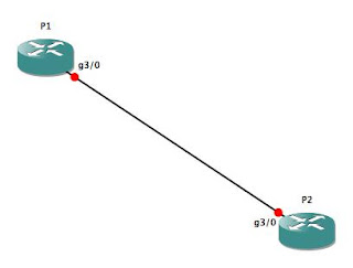
Let's start with the core. Since I am mocking this lab up in GNS3 on a laptop with only 4GB of RAM, the core is going to be very simple: just two routers (P1 and P2), with a single Gig-E connection between them:


As I mentioned in the previous MPLS lab, we must be running CEF in order to run MPLS, so before anything else, make sure you've enabled CEF on the two core routers. Then, we'll put IP addresses on Gig3/0 on both P1 and P2, and configure a Loopback IP address, as well:

P1(config)#ip cef
P1(config)#int lo0
P1(config-if)#ip addr 10.254.254.1 255.255.255.255
P1(config-if)#no shut
P1(config-if)#int gig3/0
P1(config-if)#ip addr 10.0.0.1 255.255.255.252
P1(config-if)#no shut
P1(config-if)#

From this, I'm sure you can figure out how to configure P2 (basically, find any IP address that ends in ".1" and replace it with ".2"), so I won't belabor the point with a full config for P2 here.

Next, we will need to enable MPLS on Gig3/0 on both routers, and turn up OSPF so that our core and provider edge routers can route to each other:

P1(config-if)#int gig3/0
P1(config-if)#mpls ip
P1(config-if)#router ospf 42
P1(config-router)#router-id 10.254.254.1
P1(config-router)#network 10.0.0.0 0.0.0.3 area 0.0.0.0
P1(config-router)#redist conn sub
P1(config-router)#exit
P1(config)#

Once you've made the equivalent changes on P2, you should see the following output on both routers:

*Dec 16 11:40:01.311: %OSPF-5-ADJCHG: Process 42, Nbr 10.254.254.2 on GigabitEthernet3/0 from LOADING to FULL, Loading Done
P1(config)#
*Dec 16 11:40:10.767: %LDP-5-NBRCHG: LDP Neighbor 10.254.254.2:0 (1) is UP
P1(config)#

With that, your P (core) routers are essentially done. You will need to turn up interfaces to connect to your PE (edge) routers -- don't forget the "mpls ip" command on those interfaces! -- and you'll need to establish routing between the P and PE routers, but that should be old hat by now.

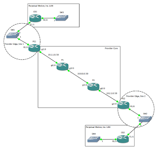
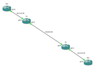
Let's move on to the PE routers. We will connect PE1 to P1, and PE2 to P2, like so...:


...using the following configs:
PE1:
PE1(config)#ip cef
PE1(config)#router ospf 42
PE1(config-router)#router-id 10.254.254.3
PE1(config-router)#int lo0
PE1(config-if)#ip addr 10.254.254.3 255.255.255.255
PE1(config-if)#no shut
PE1(config-if)#ip ospf 42 area 0.0.0.0
PE1(config-if)#int gig2/0
PE1(config-if)#mpls ip
PE1(config-if)#ip addr 10.1.1.2 255.255.255.252
PE1(config-if)#no shut
PE1(config-if)#ip ospf 42 area 0.0.0.0

...and...:

PE2:
PE2(config)#ip cef
PE2(config)#router ospf 42
PE2(config-router)#router-id 10.254.254.4
PE2(config-router)#int lo0
PE2(config-if)#ip addr 10.254.254.4 255.255.255.255
PE2(config-if)#ip ospf 42 area 0.0.0.0
PE2(config-if)#no shut
PE2(config-if)#int gig2/0
PE2(config-if)#mpls ip
PE2(config-if)#ip addr 10.2.1.2 255.255.255.252
PE2(config-if)#ip ospf 42 area 0.0.0.0
PE2(config-if)#no shut

Once you've gotten this far, you should see output similar to this as the various adjacencies come up:

*Dec 16 11:58:31.063: %OSPF-5-ADJCHG: Process 42, Nbr 10.254.254.2 on GigabitEthernet2/0 from LOADING to FULL, Loading Done
*Dec 16 11:58:41.499: %LDP-5-NBRCHG: LDP Neighbor 10.254.254.2:0 (1) is UP

Let's check our routing tables and LDP database to make sure everything is working as expected:

PE1#sho ip route
Codes: C - connected, S - static, R - RIP, M - mobile, B - BGP
       D - EIGRP, EX - EIGRP external, O - OSPF, IA - OSPF inter area
       N1 - OSPF NSSA external type 1, N2 - OSPF NSSA external type 2
       E1 - OSPF external type 1, E2 - OSPF external type 2
       i - IS-IS, su - IS-IS summary, L1 - IS-IS level-1, L2 - IS-IS level-2
       ia - IS-IS inter area, * - candidate default, U - per-user static route
       o - ODR, P - periodic downloaded static route

Gateway of last resort is not set

     10.0.0.0/8 is variably subnetted, 7 subnets, 2 masks
O E2    10.254.254.2/32 [110/20] via 10.1.1.1, 00:10:26, GigabitEthernet2/0
C       10.254.254.3/32 is directly connected, Loopback0
O       10.2.1.0/30 [110/3] via 10.1.1.1, 00:10:26, GigabitEthernet2/0
C       10.1.1.0/30 is directly connected, GigabitEthernet2/0
O       10.0.0.0/30 [110/2] via 10.1.1.1, 00:10:26, GigabitEthernet2/0
O E2    10.254.254.1/32 [110/20] via 10.1.1.1, 00:10:26, GigabitEthernet2/0
O       10.254.254.4/32 [110/4] via 10.1.1.1, 00:05:29, GigabitEthernet2/0
PE1#sho mpls ldp neigh
    Peer LDP Ident: 10.254.254.1:0; Local LDP Ident 10.254.254.3:0
    TCP connection: 10.254.254.1.646 - 10.254.254.3.53411
    State: Oper; Msgs sent/rcvd: 22/21; Downstream
    Up time: 00:10:33
    LDP discovery sources:
      GigabitEthernet2/0, Src IP addr: 10.1.1.1
        Addresses bound to peer LDP Ident:
          10.0.0.1        10.254.254.1    10.1.1.1        
PE1#sho mpls ldp bindings
  lib entry: 10.0.0.0/30, rev 8
    local binding:  label: 17
    remote binding: lsr: 10.254.254.1:0, label: imp-null
  lib entry: 10.1.1.0/30, rev 4
    local binding:  label: imp-null
    remote binding: lsr: 10.254.254.1:0, label: imp-null
  lib entry: 10.2.1.0/30, rev 6
    local binding:  label: 16
    remote binding: lsr: 10.254.254.1:0, label: 17
  lib entry: 10.254.254.1/32, rev 12
    local binding:  label: 19
    remote binding: lsr: 10.254.254.1:0, label: imp-null
  lib entry: 10.254.254.2/32, rev 10
    local binding:  label: 18
    remote binding: lsr: 10.254.254.1:0, label: 16
  lib entry: 10.254.254.3/32, rev 2
    local binding:  label: imp-null
    remote binding: lsr: 10.254.254.1:0, label: 18
  lib entry: 10.254.254.4/32, rev 14
    local binding:  label: 20
    remote binding: lsr: 10.254.254.1:0, label: 19
PE1#

With this, you now have a fully-functional "service provider" MPLS network. Your core is up, your PE routers are up, they are all sharing routes, and they have created LDP bindings between the routers. Sweet! All we need now are some customers to connect to our network so that the provider edge routers can start earning their keep ;)

This is where things start to get fun. Suppose the CIO for Perpetual Motion, Inc., an alternative energy provider, approaches you for connectivity across your network. You will turn up an interface for Perpetual Motion on both PE1 and PE2, and create a VRF to isolate Perpetual Motion's network instance from both your own network, as well as from any future customers' networks. Your network now looks like this...:


...with the following config changes on PE1 and PE2:
PE1:
PE1(config)#ip vrf PERPETUAL
PE1(config-vrf)#rd 65000:20
PE1(config-vrf)#route-target both 65000:20
PE1(config-vrf)#int fa0/0
PE1(config-if)#no ip addr
PE1(config-if)#no shut
PE1(config-if)#int fa0/0.20
PE1(config-subif)#encap dot1q 20
PE1(config-subif)#ip vrf forwarding PERPETUAL
PE1(config-subif)#ip addr 100.64.20.1 255.255.255.252
PE1(config-subif)#no shut

PE2:
PE2(config)#ip vrf PERPETUAL
PE2(config-vrf)#rd 65000:20
PE2(config-vrf)#route-target both 65000:20
PE2(config-vrf)#int fa0/0
PE2(config-if)#no ip addr
PE2(config-if)#no shut
PE2(config-if)#int fa0/0.20
PE2(config-subif)#encap dot1q 20
PE2(config-subif)#ip vrf forwarding PERPETUAL
PE2(config-subif)#ip addr 100.64.20.5 255.255.255.252
PE2(config-subif)#no shut

It isn't necessary to turn up a dot-1q encapsulated sub-interface here. We just as easily could turn up a new physical interface for every customer...until we ran out of physical interfaces. Since this is a lab in GNS3, it's not very likely that we would, in fact, run out of physical interfaces (unless you are far more ambitious than I, in which case, you do you!). However, this is pretty much how we provided service to customers at one of my former places of employment, given that SW1 and SW2 could be either actual Ethernet switches or some other kind of Metro-Ethernet network extender (Actelis, Accedian, AdTran, Cisco ME-3400, etc.) or combination thereof. Once the customer configures their routers, we should have point-to-point connectivity between CE1 and PE1, and between CE2 and PE2:

CE1:
CE1#sho run
interface Loopback0
ip address 192.168.254.1 255.255.255.255
ip ospf 1138 area 0.0.0.0
!
interface FastEthernet0/0
ip address 192.168.1.1 255.255.255.0
ip ospf 1138 area 0.0.0.0
!
interface FastEthernet1/1
ip address 100.64.20.2 255.255.255.252
ip ospf network point-to-point
ip ospf 1138 area 0.0.0.0
!
router ospf 1138
router-id 192.168.254.1
log-adjacency-changes
passive-interface FastEthernet0/0
passive-interface Loopback0
!
^c CE1#ping 100.64.20.1
Sending 5, 100-byte ICMP Echos to 100.64.20.1, timeout is 2 seconds:
.!!!!
Success rate is 80 percent (4/5), round-trip min/avg/max = 20/24/32 ms
CE1#

All that is left now is to set up routing between CE1 and CE2. On PE1 and PE2, we will set up an instance of OSPF to accept routes from CE1 and CE2, respectively:

PE1(config-subif)#router ospf 20 vrf PERPETUAL
PE1(config-router)#router-id 100.64.20.1
PE1(config-router)#network 100.64.20.0 0.0.0.3 area 0.0.0.0
PE1(config-subif)#
*Dec 16 14:09:43.579: %OSPF-5-ADJCHG: Process 20, Nbr 192.168.254.1 on FastEthernet0/0.20 from LOADING to FULL, Loading Done
PE1(config-subif)#

CE1(config-if)#router ospf 1138
CE1(config-router)#router-id 100.64.20.2
CE1(config-router)#network 100.64.20.0 0.0.0.3 area 0.0.0.0
CE1(config-router)#int lo0
CE1(config-if)#ip ospf 1138 area 0.0.0.0
CE1(config-if)#int fa0/0
CE1(config-if)#ip ospf 1138 area 0.0.0.0

Now, does it work?

PE1#sho ip route vrf PERPETUAL
...
Gateway of last resort is not set

     100.0.0.0/30 is subnetted, 1 subnets
C       100.64.20.0 is directly connected, FastEthernet0/0.20
     192.168.254.0/32 is subnetted, 1 subnets
O       192.168.254.1 [110/2] via 100.64.20.2, 00:01:40, FastEthernet0/0.20
O    192.168.1.0/24 [110/2] via 100.64.20.2, 00:01:30, FastEthernet0/0.20
PE1#

Looks good! We've got the loopback and Fa0/0 IP addresses in our routing table, so as you can see, all we need to do to set up a customer routing instance on our PE routers is to append "vrf <VRF NAME> to the end of the "router ospf..." statements.

The last step is to set up a multiprotocol BGP process between PE1 and PE2 so that they can share the customer routes between them, then configure redistribution to the OSPF process in the customer VRF. If that sounds complicated, don't worry; it's really not terribly difficult:

PE1:
PE1(config)#router bgp 65000
PE1(config-router)#no synch
PE1(config-router)#neighbor 10.254.254.4 remote-as 65000
PE1(config-router)#neighbor 10.254.254.4 update-source Loopback0
PE1(config-router)#address-family vpnv4
PE1(config-router-af)#neighbor 10.254.254.4 activate
PE1(config-router-af)#neighbor 10.254.254.4 send-community extended
PE1(config-router-af)#exit
PE1(config-router)#address-family ipv4 vrf PERPETUAL
PE1(config-router-af)#redist ospf 20 vrf PERPETUAL
PE1(config-router-af)#no synch
PE1(config-router-af)#exit
PE1(config-router)#exit
PE1(config)#router ospf 20 vrf PERPETUAL
PE1(config-router)#redist bgp 65000 subnets

PE2:
PE2(config)#router bgp 65000
PE2(config-router)#no sync
PE2(config-router)#neighbor 10.254.254.3 remote-as 65000
PE2(config-router)#neighbor 10.254.254.3 update-source Loopback0
PE2(config-router)#address-family vpnv4
PE2(config-router-af)#neighbor 10.254.254.3 activate
PE2(config-router-af)#neighbor 10.254.254.3 send-community extended
PE2(config-router-af)#exit
PE2(config-router)#address-family ipv4 vrf PERPETUAL
PE2(config-router-af)#redist ospf 20 vrf PERPETUAL
PE2(config-router-af)#no sync
PE2(config-router-af)#exit
PE2(config-router)#exit
PE2(config)#router ospf 20 vrf PERPETUAL
PE2(config-router)#redist bgp 65000 sub
PE2(config-router)#exit


Let's check our CE routers and see if they are propagating routes correctly:

CE1#sho ip route
Gateway of last resort is not set

     100.0.0.0/30 is subnetted, 2 subnets
C       100.64.20.0 is directly connected, FastEthernet1/1
O IA    100.64.20.4 [110/2] via 100.64.20.1, 00:02:43, FastEthernet1/1
     192.168.254.0/32 is subnetted, 2 subnets
O IA    192.168.254.2 [110/3] via 100.64.20.1, 00:02:43, FastEthernet1/1
C       192.168.254.1 is directly connected, Loopback0
C    192.168.1.0/24 is directly connected, FastEthernet0/0
O IA 192.168.2.0/24 [110/3] via 100.64.20.1, 00:02:43, FastEthernet1/1
CE1#

CE2:
CE2#sho ip route
Gateway of last resort is not set

     100.0.0.0/30 is subnetted, 2 subnets
O IA    100.64.20.0 [110/2] via 100.64.20.5, 00:02:27, FastEthernet1/1
C       100.64.20.4 is directly connected, FastEthernet1/1
     192.168.254.0/32 is subnetted, 2 subnets
C       192.168.254.2 is directly connected, Loopback0
O IA    192.168.254.1 [110/3] via 100.64.20.5, 00:02:27, FastEthernet1/1
O IA 192.168.1.0/24 [110/3] via 100.64.20.5, 00:02:27, FastEthernet1/1
C    192.168.2.0/24 is directly connected, FastEthernet0/0
CE2#

Yep, on CE1, I can see the Loopback and Fa0/0 IP addresses from CE2, and vice versa. It looks like MPLS is working properly, and like our routing processes are sharing routes in the proper VRF's.

By configuring the P, then PE and CE routers one at a time, it should be fairly obvious how each class of router differs from the others (at least, from a configuration standpoint). The CE routers are the simplest of all, in that they are completely agnostic about the underlying architecture of the service provider network. All they need to do is set up routing, either with a dynamic routing protocol like OSPF or via static routes, with the provider; no special configuration is required on the CE routers at all. Next, in order of complexity, are the P routers. The only additional configuration they require is the "mpls ip" statement in any interface that will be part of the MPLS core. Most of the magic happens in the PE routers, which is reflected in the relative complexity of the PE routers' configs. This is where we create the VRFs, set the route distinguisher and route targets, configure the VRF-aware routing protocols, and set up BGP to redistribute the routes across the core.

Advanced Cisco Routing: DMVPN -- Point-to-Multipoint VPN Tunneling

A few years ago, I used to work for a service provider that operated in rural Alaska. By lower-48 standards, our network wasn’t terribly large — or at least, the logical topology wasn’t terribly large; the physical topology covered a rather large geographical region. Our major hub was a huge, bustling metropolis of about 5,000 (!) people.

This site also was where we located our hub router for the network. We had an extension site in Anchorage (naturally, since that was where most of our employees lived and worked), the hub site, a PoP at the hub site hanging off the hub router, and then multiple PoPs scattered across our service area, also linked off of the hub router. Because our own management network was built across our own service-provider network, we set up VPN tunnels from the hub router to each and every one of our sub-tended sites to provide secure management access to our network. Conceptually, it was a very simple model (and honestly, it might have been the only model our equipment would support at the time), but if you think that configuring a separate VPN tunnel for each site could be a bit of a chore, you are exactly right.

As I’m sure you’ve guessed by now, there is A Better Way to achieve these goals, a way that makes configuring and managing multiple sites sub-tended off of a single hub much less time consuming. Allow me to introduce you to DMVPN’s (Dynamic Multipoint VPN’s). As always, we’ll start with our network diagram:


R1 through R4 will be our management network, with R1 being the hub and R2 — R4 being the spokes. R5, R6 and R7 are the service provider network. In the real network that I managed, we had static, default routes on R1 through R4, and ran OSPF on our provider network. In this lab, we will run OSPF internally on both networks, and peer the management and provider networks with BGP, since that is a more common scenario for most people (being both provider and customer is fairly unusual). Also, running OSPF over a DMVPN topology introduces a few wrinkles that are worth covering, but I’m getting ahead of myself ;)

For addressing, I’ll be using 100.64.x.x addresses in place of public IP address ranges, and 192.168.x.0/24 for the inside interfaces on my management network. I’ll use 172.16.x.x IP space for the tunnel addressing. On the "Internet" routers, I’ll use 100.64.254.x/32 for the Loopback IP addresses, while 10.254.254.x/32 will be the Loopback IP addresses on my management routers.

Still with me? Good! Let’s start by setting up basic connectivity to each router, starting with the Internet routers (since there is nothing new on them):

R5:
interface Loopback0
ip address 100.64.254.5 255.255.255.255
no shut
!
interface FastEthernet0/0
ip address 100.64.0.1 255.255.255.252
no shut
!
interface FastEthernet0/1
ip address 100.64.0.5 255.255.255.252
no shut
!
interface FastEthernet1/0
ip address 100.64.0.9 255.255.255.252
no shut
!
router ospf 1138
router-id 100.64.254.5
log-adjacency-changes
passive-interface Loopback0
network 100.64.0.0 0.0.0.3 area 0.0.0.0
network 100.64.0.4 0.0.0.3 area 0.0.0.0
network 100.64.0.8 0.0.0.3 area 0.0.0.0
network 100.64.254.5 0.0.0.0 area 0.0.0.0
!

R6 and R7 are similar, and since there is nothing new here, I’ll skip those configs.

We’ll go ahead and configure the IP addressing on the FastEthernet and Loopback interfaces of R1, R2, R3 and R4 next. Again, nothing new, and nothing exciting, so I won’t belabor the config here, but make sure R1, R2, R3 and R4 can ping their respective gateways before proceeding. Once point-to-point connectivity between the management network and the service provider network is working, we’ll set up BGP peering between R1 and R5, R2 and R6, R3 and R5, and finally, R4 and R7:

R1:
router bgp 65511
bgp router-id 100.64.0.2
network 100.64.0.0 mask 255.255.255.252
neighbor 100.64.0.1 remote-as 65512
neighbor 100.64.0.1 activate

R5: router bgp 65512
bgp router-id 100.64.0.1
network 100.64.0.0 mask 255.255.255.252
neighbor 100.64.0.2 remote-as 65511
neighbor 100.64.0.2 activate
redist ospf 1138 metric 120
!
router ospf 1138 redist bgp 65512 sub metric 120
!

As you can see, the configurations are almost identical, aside from swapping the AS’ in the "router bgp..." and "neighbor..." statements, and swapping the IP addresses in the "bgp router-id..." and "neighbor..." statements. Also, on R5, we are redistributing the routes learned via BGP into OSPF. We are also redistributing OSPF routes into the BGP process. R6 and R7 will be configured similarly to R5, and R2, R3 and R4 will be configured similarly to R1. Again, nothing new so far.

But now, things will start to get interesting. Let’s set up the GRE tunnel on R1:

interface Tunnel0
ip address 172.16.0.1 255.255.255.0
ip nhrp map multicast dynamic
ip nhrp network-id 1
tunnel source 100.64.0.2
tunnel mode gre multipoint
no shut
!

Just like a normal GRE tunnel, we start with "interface Tunnel <blah>", and assign an IP address to the tunnel interface. Unlike a normal tunnel interface, we are assigning a /24. You can use whatever size subnet you want, but since it is a multipoint tunnel, it should probably be larger than a /30. The "tunnel source..." statement should look familiar also (if not, see the GRE Tunnel lab for a refresher).

However, there are a few differences between a DMVPN tunnel config and a standard, point-to-point tunnel config. One of the first things you’ll likely notice is that we have not specified any of the opposite endpoints. Instead, we used the command "tunnel mode gre multipoint" to explicitly state that we are creating a point-to-multipoint (hub-and-spoke) network. That’s the "dynamic" portion of the "Dynamic Multipoint VPN. Basically, the hub accepts tunnel requests from multiple spoke routers, and automatically establishes the tunnels on demand.

You'll also notice that, even though there are three spoke routers, the hub only has one tunnel interface. That's the "Multipoint" portion of the acronym ;) This raises a very interesting question. In a point-to-point circuit, it is trivial to determine the IP address of the next hop (if you are on a /30 or /31 network, there are only two usable IP addresses, and you are using one of them, right?). However, in a multipoint network, your tunnel interfaces are in a larger subnet. In our example, we are using a /24, meaning the other end of the tunnel could be any one of 253 possible IP addresses! How does the hub router know which IP address corresponds to which tunnel? If you look at the next two lines of the tunnel config, you’ll see the two "ip nhrp..." statements. NHRP ("Next Hop Resolution Protocol," see also CCIE or Null! for a good discussion on the topic) is the protocol that we use to determine the IP address of the other side of the multipoint tunnel. In much the same way that ARP maps IP addresses to Ethernet addresses, NHRP allows our routers to dynamically map IP addressing to the multipoint tunnels. In the "ip nhrp map multicast dynamic" statement, we are telling NHRP to dynamically create these mappings for our multipoint tunnels. However, you might have multiple tunnels on any given router, so by specifying different network ID's with the "ip nhrp network-id ..." statement, you can create multiple hub-and-spoke networks without them conflicting with one another. That’s it for the hub router. That wasn't too bad, was it?

We’ll use R2 as an example of the spoke router configuration; R3 and R4 will be very similar:

R2:
interface Tunnel0
ip address 172.16.0.2 255.255.255.0
ip nhrp map 172.16.0.1 100.64.0.2
ip nhrp map multicast 100.64.0.2
ip nhrp network-id 1
ip nhrp nhs 172.16.0.1
tunnel source 100.64.0.14
tunnel mode gre multipoint
no shut
!

Like the hub router, the spoke router contains the "ip address...," "tunnel source..." and "tunnel mode gre multipoint commands." It also contains a handful of "ip nhrp..." statements, but they are slightly more complex. First, the spoke router must know how to reach the hub router in order to send the tunnel request, so we start by telling the tunnel to create a connection to the IP address of the hub router’s outside interface (the tunnel source on the hub router). In other words, to reach 172.16.0.1 (the tunnel IP address on R1) use 100.64.0.2 (Fa1/0 on R1). Next, "ip nhrp map multicast 100.64.0.2" sets 100.64.0.2 (Fa1/0 on R1) as the destination for multicast or broadcast packets sent across the non-broadcast, multi-access, or NBMA, (ie., the DMVPN) network. If multicast or broadcast packets are sent across the NBMA network, R1 is responsible for forwarding them to other hosts participating in the network, so we are telling the tunnel interface to forward those packets to R1. The last new command on the spoke router is the "ip nhrp nhs 172.16.0.1" statement. With this line, we are telling the spoke router to use the "next-hop server" to forward traffic across the NBMA network.

Substitute the appropriate values for the IP address and tunnel source on R3 and R4, and you should have working tunnels between R1 and each of the spoke routers. To verify this, use the "sho dmvpn" command:

R2#sho dmvpn
Legend: Attrb --> S - Static, D - Dynamic, I - Incomplete
    N - NATed, L - Local, X - No Socket
    # Ent --> Number of NHRP entries with same NBMA peer
    NHS Status: E --> Expecting Replies, R --> Responding
    UpDn Time --> Up or Down Time for a Tunnel
==========================================================================

Interface: Tunnel0, IPv4 NHRP Details

IPv4 NHS: 172.16.0.1 RE
Type:Spoke, Total NBMA Peers (v4/v6): 1

# Ent  Peer NBMA Addr Peer Tunnel Add State  UpDn Tm Attrb    Target Network
----- --------------- --------------- ----- -------- ----- -----------------
    1     100.64.0.2      172.16.0.1    UP 01:21:34    S      172.16.0.1/32


R2#

As you can see from the snippet of output above, R2 has now established a tunnel connection to R1 (tunnel state is "Up" and next to "IPV4 NHS, we have the IP address of int tunnel0 on R1, followed by the flags "RE," verifying that the tunnel is responding and expecting replies). After duplicating the tunnel config on R3 and R4, you should see similar output on those routers, although each router will only show the connection to R1. This is a point-to-multipoint network, meaning that R2 cannot talk directly to R3 without going through R1 (sort of...actually R1 can broker connections between the spokes, but honestly, I’m not comfortable enough with the topic to go there yet). Assuming that you have copied the modified version of R2’s tunnel config to R3 and R4, you should have a completed point-to-multipoint VPN network now (w00t!). However, if you try to ping from the inside interface of R2, R3 or R4 to the inside interface of R1, you will most likely not be thrilled with the result:

R4#ping 192.168.1.1 source 192.168.4.1
<...snip...>
.....
Success rate is 0 percent (0/5)
R4#

Any ideas why? Of course! We haven’t set up any routing between the inside networks. When we configured BGP peering between the management network and the service provider network, we only advertised the outside interfaces of R1, R2, R3 and R4, since our service provider should not be aware of the inner workings of our network (unless we are using MPLS). In order to actually send traffic across the VPN tunnels, we need to enable a routing protocol over the tunnels. Easy enough, right? It should look something like this...:

R1:
router ospf 42
router-id 10.254.254.1
passive-interface default
no passive-interface Tunnel0
network 10.254.254.1 0.0.0.0 area 0.0.0.0
network 172.16.0.0 0.0.0.255 area 0.0.0.0
network 192.168.1.0 0.0.0.255 area 0.0.0.0

Again, after making the appropriate substitutions for the router-id and the advertised networks, we’ll make the same changes on the spoke routers, and...what is going on here?

R1(config)#
*Dec 13 15:44:15.947: %OSPF-5-ADJCHG: Process 42, Nbr 10.254.254.3 on Tunnel0 from LOADING to FULL, Loading Done
*Dec 13 15:44:16.391: %OSPF-5-ADJCHG: Process 42, Nbr 10.254.254.3 on Tunnel0 from FULL to DOWN, Neighbor Down: Adjacency forced to reset
R1(config)#
*Dec 13 15:44:20.483: %OSPF-5-ADJCHG: Process 42, Nbr 10.254.254.2 on Tunnel0 from INIT to DOWN, Neighbor Down: Adjacency forced to reset
*Dec 13 15:44:20.535: %OSPF-5-ADJCHG: Process 42, Nbr 10.254.254.3 on Tunnel0 from EXSTART to DOWN, Neighbor Down: Adjacency forced to reset
*Dec 13 15:44:20.699: %OSPF-5-ADJCHG: Process 42, Nbr 10.254.254.4 on Tunnel0 from LOADING to FULL, Loading Done
R1(config)#
*Dec 13 15:44:22.735: %OSPF-5-ADJCHG: Process 42, Nbr 10.254.254.4 on Tunnel0 from FULL to DOWN, Neighbor Down: Adjacency forced to reset
R1(config)#
*Dec 13 15:44:25.307: %OSPF-5-ADJCHG: Process 42, Nbr 10.254.254.3 on Tunnel0 from LOADING to FULL, Loading Done
*Dec 13 15:44:25.555: %OSPF-5-ADJCHG: Process 42, Nbr 10.254.254.3 on Tunnel0 from FULL to DOWN, Neighbor Down: Adjacency forced to reset
R1(config)#

Why is OSPF flapping?!?!

This is where I start to get in a little bit over my head. If I understand correctly, the issue is that OSPF is aware of the type of network configured across each OSPF-aware link. In this case, we have configured a NBMA network via multipoint GRE tunnels, but OSPF considers GRE tunnels to be a point-to-point network. While we had OSPF only running between R1 and R2, this was fine, but as soon as OSPF sees two neighbors across a single "point-to-point" link, it gets confused (understandably so!) and drops the neighbor relationship. To resolve this problem, at least under certain circumstances, make the following change to R1, R2, R3 and R4:
int tunnel 0
ip ospf network point-to-multipoint

Now that OSPF understands that int Tunnel0 is actually part of a multipoint network, it will allow all three spoke routers to participate in OSPF across the tunnel. Run "sho ip route" and "sho ip ospf neighbor" to verify that everything is working as expected (it should be), and you should be good to go!

Wednesday, November 23, 2016

IPv6 Intro: Access Control Lists

Way back in CCNA Lesson 13, we introduced Access Control Lists (ACL's) on Cisco routers. Since Cisco has re-vamped the CCNA test to include IPv6, it is probably worth adding another lab to revisit ACL's when using IPv6. The good news is, ACL's in IPv6 are very similar to IPv4 ACL's, but not quite as complicated. Forget all of that jazz about named ACL's, numbered ACL's, standard ACL's and extended ACL's -- in IPv6, you get named ACL's...period. Ready to take a peek? Let's get started!

Suppose you have two routers, R1 and R2. R1 has two clients connected to it, Clone 1 and Clone 2. R2 has two servers connected to it, CentOS and CentOS_Clone. Since I happen to like coffee, and I don't like remembering long strings of hexadecimal digits, I have based my addressing scheme in this lab on the base address 2001:C0:FFEE::x/y :


Since we are using SLAAC to configure our host IP addresses, we will still have to deal with some ugly addressing, but at least the routers won't be too terribly bad.

So...suppose we want to allow Clone 2 to log in to our routers, but we don't want any other network hosts to log in. Just as we would do in IPv4, we will create an access list to filter incoming traffic, then apply it to the "line vty 0 4" configuration. First, we need the IPv6 address of Clone 2:


...then, we create an access control list to permit this traffic:
R2(config)#ipv6 access-list ?
  WORD        User selected string identifying this access list
  log-update  Control access list log updates

R2(config)#ipv6 access-list PROTECT-CP ?
  <cr>

R2(config)#ipv6 access-list PROTECT-CP
R2(config-ipv6-acl)#permit ipv6 host 2001:C0:FFEE:1:A00:27FF:FE47:85D3 host 2001:C0:FFEE:254::2
R2(config-ipv6-acl)#

Then, we apply the ACL to the "line vty 0 4" configuration:
R2(config-ipv6-acl)#line vty 0 4
R2(config-line)#access-class PROTECT-CP in

Pretty easy! Let's test it...:


Good...but does the ACL deny traffic from other hosts? Let's check it from Clone 1 and see:


Perfect! Let's see if we can control access to the web servers behind R2 with ACL's. We'll start by creating a new ACL to filter HTTP traffic to CentOS6, but not to CentOS6_Clone:
R2(config)#ipv6 access-list NO-HTTP-ACCESS
R2(config-ipv6-acl)#deny tcp host 2001:C0:FFEE:1:A00:27FF:FED3:7C8F host 2001:C0:FFEE:2:A00:27FF:FE7D:F08D eq 80
R2(config-ipv6-acl)#permit ipv6 any any
R2(config-ipv6-acl)#exit
R2(config)#int fa1/0
R2(config-if)#ipv6 acc?
% Unrecognized command
R2(config-if)#ipv6 ?  
IPv6 interface subcommands:
  address         Configure IPv6 address on interface
  cef             Cisco Express Forwarding for IPv6
  dhcp            IPv6 DHCP interface subcommands
  enable          Enable IPv6 on interface
  mfib-cef        MFIB CEF-based forwarding
  mld             interface commands
  mtu             Set IPv6 Maximum Transmission Unit
  nd              IPv6 interface Neighbor Discovery subcommands
  ospf            OSPF interface commands
  pim             PIM interface commands
  redirects       Enable sending of ICMP Redirect messages
  rip             Configure RIP routing protocol
  traffic-filter  Access control list for packets
  unnumbered      Preferred interface for source address selection
  verify          Enable per packet validation

Despite so much of our understanding of IPv4 transferring directly (or nearly so...) to IPv6, this is where things change a little. In IPv6, we use a different statement to apply an IPv6 ACL to an interface:
R2(config-if)#ipv6 traffic-filter NO-HTTP-ACCESS in
R2(config-if)#exit

Don't ask me; I didn't create the syntax ;)

Let's see if it works. On Clone 1:


As you can see in the screenshot, there are two browser windows open. In the browser window trying to connect to the web server that we filtered on R2 (IPv6 address ...F08D), the browser has returned an error message stating that it cannot create a connection to the web server. In the browser window connected to the second web server (IPv6 address ending in ...31B9), we are able to load an image gallery. "But," I can hear you object, "all that proves is that we have blocked access to a particular server. The point was to block access to that server from a selected host." So, let's see if we can access both servers from a second client:


As you can see, Clone 2 has unrestricted access to both web servers, proving that the ACL is indeed restricting access from Clone 1 to CentOS6, as required (yes, I could have simply removed the ACL from the router before trying Clone 2, and the only way you'll know for sure is to fire up your own router or simulator and try it yourself! ;)

Monday, November 7, 2016

Advanced Cisco Configuration: Access Ports, Trunk Ports and Native VLANs

I ran into a very interesting problem today that, in hindsight, was rather obvious. Suppose we have a router with a switchport module in one of its open slots connected to a managed switch. Let's use FastEthernet0/15 for the switchport module interface connected to FastEthernet0/0 on the standalone switch. Fa0/15 on the router's switchport module is configured as an access port on some particular VLAN, say VLAN 10, and Fa0/0 on the standalone switch is configured as a trunk port on some different VLAN, say 238. The problem came to my attention because the log files on the router were filling up with errors along the lines of this:
01:48:19: %CDP-4-NATIVE_VLAN_MISMATCH: Native VLAN mismatch discovered on FastEthernet0/15...

At first glance, I was somewhat confused by this because the CDP error message suggested that the Native VLAN's on the two switchports didn't match (the standalone switch had the native VLAN left at its default, or VLAN 1). I didn't have access to the switch, so I couldn't look at its configuration, but I knew that a trunk port on the switch could NOT communicate with the access port on the router's switch module. What, then, were the techs who originally set this up trying to accomplish? With the VLAN mismatch, there shouldn't have been any traffic flowing from the switch to the router, right?

Well, no.

After mocking things up in GNS3 as well as in hardware with a spare 3825 and a Catalyst 2950 at my desk, I was able to figure out what was actually happening. In short, the managed switch was sending Ethernet frames with a VLAN tag out Fa0/0, which the router was dutifully discarding, since it was expecting untagged frames. However, any traffic on VLAN 1 -- the default native VLAN -- on the switch was being sent out of Fa0/0 as untagged frames...which the router happily accepted as belonging to VLAN 10 when they entered Fa0/15. CDP wasn't happy about this, since it could tell that the native VLAN on the managed switch wasn't the same as the VLAN configured on router's switchport, but since configuring a port as an access port means, "accept any untagged Ethernet frames coming in to this port, and place them in VLAN 10," traffic was still flowing between the switch and the router.

Needless to say, this is bad practice and is very insecure. If you don't match up the native VLAN's between Layer-2 devices, it is very easy to allow traffic across your network that you didn't intend. Even worse, VLAN 1 is the default management VLAN on Cisco switches, so essentially, you are allowing traffic that is supposed to be in one VLAN into the management VLAN on the standalone switch (!). This is why CDP raises an alarm about misconfigurations such as this: in all likelihood, something is happening that you did not intend. In fact, when I mocked this up on a pair of 3640 routers with NM16-ESW switch modules in GNS3, spanning-tree on the 3640 disabled the port until I disabled spanning tree on the affected VLAN:
00:21:54: %SPANTREE-7-RECV_1Q_NON_TRUNK: Received 802.1Q BPDU on non trunk FastEthernet0/15 VLAN106.
00:21:54: %SPANTREE-7-BLOCK_PORT_TYPE: Blocking FastEthernet0/15 on VLAN106. Inconsistent port type.
R1(config)#no spanning-tree vlan 106

Interestingly enough, the router didn't complain when I set up the connected interfaces as access ports in different VLAN's -- it was only once the router received an Ethernet frame with an 802.1Q VLAN tag that spanning-tree disabled the port on me. Even more interesting, the physical Cisco 3825 router with a 16-port switch module and 2950 switch did not disable any ports with a similar configuration (perhaps Spanning-Tree was not running on the 3825?).

Thursday, October 27, 2016

Cisco Advanced Routing Lab: IP Service Level Agreements

So you've taken all of the pieces that we've discussed so far -- Multicast, QoS, etc. -- and built a solid network for your customers. How do you prove to your customers that they are getting the quality that they are paying for? Arguably more important, how do you keep tabs on what's happening on your network so that you can fix any problems before your customer's begin complaining about them? As I'm sure you've guessed, there is a solution that is built in to most reasonably modern versions of Cisco IOS, and that solution is called "ip sla" (service level agreements). To mock up this lab, I had to upgrade my virtual routers slightly by adding IOS images for Cisco 7200 routers, as the IOS versions I had for the 3640 and 2651 routers I've been modeling don't support the ip sla feature.

Basically, the ip sla feature sends traffic across the network to measure packet loss, latency, jitter, etc. What's nice is that ip sla's allow you to craft the packets (or datagrams) that will be sent to mimic whatever kind of traffic you want to monitor. For example, you can set the TOS markings to monitor priority traffic across the network. You can tell the IP SLA engine to send data inside the G729 codec to measure how voice traffic is affected by the network. You can specify how often to send this traffic across the network, and how many packets to send at a time. It's kind of like the ping tool on steroids ;)

Suppose you have the following network...:


Because we have clients connected to R5, and a streaming server connected through R3, we want to make sure that jitter and latency is within acceptable limits between these two routers. We could build a Smokeping server (and in fact, Smokeping is running on the server labeled "CentOS6"), but Smokeping just sends standard ICMP packets. What if we want to measure latency of UDP traffic with specific QoS markings? Smokeping can't do that. Fortunately, this is exactly the kind of problem that the ip sla feature was designed to address, so we will enable ip sla on R3 and R5:
R3#sho run | begin ip sla
ip sla responder
ip sla 10015
udp-jitter 10.254.254.5 32766 source-ip 10.254.254.3 num-packets 20
tos 184
frequency 300
ip sla schedule 10015 life forever start-time now
ip sla 10025
udp-echo 10.254.254.5 32764 source-ip 10.254.254.3
ip sla schedule 10025 life forever start-time now

...and on R5:
R5#sho run | begin ip sla
ip sla responder
ip sla 10013
udp-jitter 10.254.254.3 32766 source-ip 10.254.254.5 num-packets 20
tos 184
frequency 300
ip sla schedule 10013 life forever start-time now
ip sla 10023
udp-echo 10.254.254.3 32764 source-ip 10.254.254.5
ip sla schedule 10023 life forever start-time now

The first line, "ip sla responder" tells the router to respond to IP SLA traffic. Next, we create an IP SLA process to send traffic to remote destination. The 5-digit identifier is simply a unique identifier on that router; in my case, the first three digits were pretty much arbitrary, the fourth digit I used to separate the UDP jitter test from the UDP echo test, and the last digit was taken from the router number (i.e., xxxx3 was a query for R3, xxxx5 was a query for R5, etc.). This is perhaps overkill with the examples I've shown, but on R1, for example, I set up similar IP SLA probes for R2-R5. Next, I specified what kind of test I wanted to run ("udp-jitter, udp-echo -- there are many, many more options to choose from), the destination IP address, a random port number to probe on the destination, the source IP address to use in the outbound datagram, and the optional "num-packets" flag to specify how many packets (grrr...not to be pedantic, but UDP -> datagram, Cisco! In technical fields, precise terminology often is important </rant>). In the UDP jitter test, the next line specifies that we want to apply a TOS marking so that this packet receives the same kind of priority handling that VoIP traffic (DSCP EF) would receive. After that, I specified a frequency of one test every 5 minutes for the UDP jitter test (I left the UDP echo test at the default settings). Finally, I specified the schedule for the IP SLA probes, start now and run indefinitely. However, if you wanted to monitor performance over a weekend or for a short period during backups at night, you could specify different values:
R3(config)#ip sla schedule 10023 life ?
  <0-2147483647>  Life seconds (default 3600)
  forever         continue running forever

R3(config)#ip sla schedule 10023 life 18600 ?
  ageout      How long to keep this Entry when inactive
  recurring   Probe to be scheduled automatically every day
  start-time  When to start this entry
  <cr>

R3(config)#ip sla schedule 10023 life 18600 recurring ?
  ageout      How long to keep this Entry when inactive
  start-time  When to start this entry
  <cr>

R3(config)#ip sla schedule 10023 life 18600 recurring start-time ?
  after     Start after a certain amount of time from now
  hh:mm     Start time (hh:mm)
  hh:mm:ss  Start time (hh:mm:ss)
  now       Start now
  pending   Start pending

R3(config)#ip sla schedule 10023 life 18600 recurring start-time 23:00 ?
  <1-31>  Day of the month
  MONTH   Month of the year
  ageout  How long to keep this Entry when inactive
  <cr>

R3(config)#$dule 10023 life 18600 recurring start-time 23:00 November 1 ?
  ageout  How long to keep this Entry when inactive
  <cr>

Cool. So...what happens when you enable IP SLA monitoring on your routers?

R3#sho ip sla statistics
IPSLAs Latest Operation Statistics

IPSLA operation id: 10015
Type of operation: udp-jitter
        Latest RTT: 17 milliseconds
Latest operation start time: *00:20:17.115 AKDT Wed Oct 26 2016
Latest operation return code: OK
RTT Values:
        Number Of RTT: 19               RTT Min/Avg/Max: 1/17/51 milliseconds
Latency one-way time:
        Number of Latency one-way Samples: 0
        Source to Destination Latency one way Min/Avg/Max: 0/0/0 milliseconds
        Destination to Source Latency one way Min/Avg/Max: 0/0/0 milliseconds
Jitter Time:
        Number of SD Jitter Samples: 17
        Number of DS Jitter Samples: 18
        Source to Destination Jitter Min/Avg/Max: 0/11/39 milliseconds
        Destination to Source Jitter Min/Avg/Max: 0/8/22 milliseconds
Packet Loss Values:
        Loss Source to Destination: 1           Loss Destination to Source: 0
        Out Of Sequence: 0      Tail Drop: 0
        Packet Late Arrival: 0  Packet Skipped: 0
Voice Score Values:
        Calculated Planning Impairment Factor (ICPIF): 0
        Mean Opinion Score (MOS): 0
Number of successes: 6
Number of failures: 0
Operation time to live: Forever


IPSLA operation id: 10025
Type of operation: udp-echo
        Latest RTT: 8 milliseconds
Latest operation start time: *00:24:23.535 AKDT Wed Oct 26 2016
Latest operation return code: OK
Number of successes: 58
Number of failures: 0
Operation time to live: Forever


R3#

That is at once a lot of information and not nearly as much information as you might hope to receive. While there is a lot of output showing quite a bit of detail, this is only the results of the last test. If you want any kind of historical perspective, you will need to put in some additional work. For example, I believe that you can have the results of the IP SLA monitoring logged to a syslog server (Splunk, perhaps?), although I haven't tried that. Alternatively, you can use SNMP to pull the results, although finding the right OIDs to query is a bit of a chore.

For now, let's focus on the CLI output. First, the UDP jitter test: the executive summary of the IP SLA monitoring is presented at the very end of the output:
Voice Score Values:
        Calculated Planning Impairment Factor (ICPIF): 0
        Mean Opinion Score (MOS): 0
Number of successes: 6
Number of failures: 0

A quick Google search provides a little insight into this output. Both ICPIF and MOS attempt to provide a metric for evaluating how suitable a network is for Voice over IP telephony, with lower scores being better than higher scores.
ICPIF values numerically less than 20 are generally considered "adequate."

MOS, on the other hand, is rated on a scale from 1 to 5, with 1 being very poor quality and 5 being very good quality. Note: In my output, the given MOS score was zero. Per Cisco, this means that the "...MOS data could not be generated for the given operation."

That should be enough to get you started with IP SLA monitoring on IOS. It's definitely a feature worth checking out if you will be using Cisco routers on any kind of production network.

IPv6 Intro: BGP, OSPF and IPv6...or Maybe Just EIGRP and IPv6, smh

Being a network engineer is kind of like being Sisyphus. Just when you think you you're starting to get to the top of your game, someone moves the target on you. In fact, a writer by the name of Spencer Johnson (M.D.) wrote a book on that subject not quite 20 years ago, and even though I've never read the book, I'd guess that it's at least as relevant today as it was then. Case in point, even though I've used IPv4, OSPF, and EIGRP professionally for years, I don't have a lot of professional experience with IPv6 or BGP. To address that problem, I set up the following network in GNS3 for playing with IPv4 and IPv6 with multiple routing protocols on emulated Cisco 7200 routers:

We have R1, R2 and R3 as routers within an autonomous system, R4 a random (IPv4-only) Internet router and R5 as another (IPv6-only, this time) random Internet router. My intent was to set up BGP peering between R1, R4 and R5, and to have R1, R2 and R3 share routes via OSPF. Sounds easy enough, right?

Hahaha...no.

In a previous lab, we set up OSPFv3 (OSPF for IPv6) on Cisco 3640 routers, so I used those instruction to (try to) set up OSPFv3 on the 7200 routers:
R1(config)#int gig0/0
R1(config-if)#ipv6 ospf 42 area 0.0.0.0
                   ^
% Invalid input detected at '^' marker.

R1(config-if)#ipv6 o?
% Unrecognized command
R1(config-if)#ipv6 ?
IPv6 interface subcommands:
  address             Configure IPv6 address on interface
  authentication      authentication subcommands
...
  multicast           multicast
  nat                 Enable IPv6 NAT on interface
  nd                  IPv6 interface Neighbor Discovery subcommands
  next-hop-self       Configures IP-EIGRP next-hop-self
  policy              Enable IPv6 policy routing
  redirects           Enable sending of ICMP Redirect messages
  rip                 Configure RIP routing protocol
...

Okay...is OSPFv3 not supported on this router? As it turns out, I think it actually is, but I'll save that for another lab.

Edit: no, it's not. I mean, it is, but it isn't. The "hooks" are there to configure OSPFv3 using "ipv6 ospf <process ID>" in global configuration, but you have to have an Advanced IP Services image to run it. The SP Services image I am running isn't licensed for it, because after all, what service provider would run OSPF on their network (answer: every one I've ever worked at), grrr...

For now, I decided to try to set up EIGRP for IPv6 since, 1) it *is* supported on the 7200, and 2) it did not seem to be supported on the 3640's:
R1(config)#int gig0/0
R1(config-if)#ipv6 router eigrp 10
R1(config-rtr)#int gig1/0
R1(config-if)#ipv6 router eigrp 10
R1(config-rtr)#exit
R1(config)#exit
R1#sho run int gig0/0
Building configuration...

Current configuration : 201 bytes
!
interface GigabitEthernet0/0
ip address 66.223.227.5 255.255.255.252
duplex full
speed 1000
media-type gbic
negotiation auto
ipv6 address 2001:C0:FFEE:2::1/126
ipv6 enable
ipv6 eigrp 10
end
R1#sho ipv6 route
IPv6 Routing Table - Default - 8 entries
Codes: C - Connected, L - Local, S - Static, U - Per-user Static route
       M - MIPv6, R - RIP, I1 - ISIS L1, I2 - ISIS L2
       IA - ISIS interarea, IS - ISIS summary, D - EIGRP, EX - EIGRP external
C   2001:C0:FFEE::/126 [0/0]
     via GigabitEthernet1/0, directly connected
L   2001:C0:FFEE::1/128 [0/0]
     via GigabitEthernet1/0, receive
C   2001:C0:FFEE:2::/126 [0/0]
     via GigabitEthernet0/0, directly connected
L   2001:C0:FFEE:2::1/128 [0/0]
     via GigabitEthernet0/0, receive
LC  2001:C0:FFEE:254::1/128 [0/0]
     via Loopback0, receive
C   2016:FA:1::/64 [0/0]
     via FastEthernet6/0.20, directly connected
L   2016:FA:1::1/128 [0/0]
     via FastEthernet6/0.20, receive
L   FF00::/8 [0/0]
     via Null0, receive
R1#

Weird...why are none of my EIGRP routes showing up? I could ping across the interfaces and my IPv4 routing protocols were working as expected, but I could not get EIGRP in IPv6 to form neighbor adjacencies. What gives?

I started troubleshooting EIGRP using essentially the same toolkit I would use for IPv4...:
R1#sho ipv6 eigrp 10 neigh
IPv6-EIGRP neighbors for process 10
% EIGRP 10 is in SHUTDOWN
R1#sho ipv6 eigrp 10 int
IPv6-EIGRP interfaces for process 10
% EIGRP 10 is in SHUTDOWN
R1#

"EIGRP...is in SHUTDOWN?" I'm not familiar with that error message. WWGS ("What Would Google Say")? I quickly found a couple of tutorials on-line which showed that setting up EIGRP in IPv6 on a 7200 is a little different than setting OSPFv3 on a 3640 (go figure). Whereas OSPFv3 on a 3640 is entirely configured on the interface, EIGRP for IPv6 is a mix of interface-level commands and global config commands:
R1#conf t
Enter configuration commands, one per line. End with CNTL/Z.
R1(config)#ipv6 router eigrp 10
R1(config-rtr)#router-id 10.254.254.1
R1(config-rtr)#redistribute connected
R1(config-rtr)#passive-int default
R1(config-rtr)#no passive-int gig0/0
R1(config-rtr)#no passive-int gig1/0
R1(config-rtr)#no shut
02:35:27: %DUAL-5-NBRCHANGE: IPv6-EIGRP(0) 10: Neighbor FE80::C802:7FF:FE00:70 (GigabitEthernet1/0) is up: new adjacency
R1(config-rtr)#
02:35:38: %DUAL-5-NBRCHANGE: IPv6-EIGRP(0) 10: Neighbor FE80::C801:6FF:FEF0:70 (GigabitEthernet0/0) is up: new adjacency
R1(config-rtr)#exit
R1(config)#exit

After making eseentially the same changes on R2 and R3 (the interface names were different, but...), I saw my routes as expected:
R1#sho ipv6 route
IPv6 Routing Table - Default - 12 entries
Codes: C - Connected, L - Local, S - Static, U - Per-user Static route
       M - MIPv6, R - RIP, I1 - ISIS L1, I2 - ISIS L2
       IA - ISIS interarea, IS - ISIS summary, D - EIGRP, EX - EIGRP external
C   2001:C0:FFEE::/126 [0/0]
     via GigabitEthernet1/0, directly connected
L   2001:C0:FFEE::1/128 [0/0]
     via GigabitEthernet1/0, receive
C   2001:C0:FFEE:2::/126 [0/0]
     via GigabitEthernet0/0, directly connected
L   2001:C0:FFEE:2::1/128 [0/0]
     via GigabitEthernet0/0, receive
D   2001:C0:FFEE:3::/64 [90/28416]
     via FE80::C802:7FF:FE00:70, GigabitEthernet1/0
LC  2001:C0:FFEE:254::1/128 [0/0]
     via Loopback0, receive
D   2001:C0:FFEE:254::2/128 [90/130816]
     via FE80::C801:6FF:FEF0:70, GigabitEthernet0/0
D   2001:C0:FFEE:254::3/128 [90/130816]
     via FE80::C802:7FF:FE00:70, GigabitEthernet1/0
D   2001:C0:FFEE:2222::/64 [90/28416]
     via FE80::C801:6FF:FEF0:70, GigabitEthernet0/0
C   2016:FA:1::/64 [0/0]
     via FastEthernet6/0.20, directly connected
L   2016:FA:1::1/128 [0/0]
     via FastEthernet6/0.20, receive
L   FF00::/8 [0/0]
     via Null0, receive
R1#

Well that was more cumbersome than it should have been, but <shrug>. At least we've got EIGRP working now. BGP via IPv4 is nothing new, so I won't waste a lot of time discussing the BGP configuration for R1-R4. However, the IPv6 configuration between R1 and R5 had me swearing at Cisco:
R1(config)#router bgp 65511
R1(config-router)# neighbor 2016:FA:1::5 remote-as 65515
R1(config-router)# address-family ipv6
R1(config-router-af)#  network 2001:C0:FFEE:254:0:0:0:1/128
R1(config-router-af)#  network 2001:C0:FFEE:254:0:0:0:2/128
R1(config-router-af)#  network 2001:C0:FFEE:254:0:0:0:3/128
R1(config-router-af)#  network 2001:C0:FFEE:2:0:0:0:0/126
R1(config-router-af)#  network 2001:C0:FFEE:0:0:0:0:0/126
R1(config-router-af)#  network 2001:C0:FFEE:2222:0:0:0:0/64
R1(config-router-af)#  network 2001:C0:FFEE:3:0:0:0:0/64
R1(config-router-af)#  neighbor 2016:FA:1::5 activate
% BGP context not been initialized properly.
R1(config-router-af)# exit
R1(config-router)#exit
R1(config)#exit
R1#sho bgp ipv6 unicast neighbors

R1#sho run | begin router bgp
router bgp 65511
bgp router-id 10.254.254.1
bgp log-neighbor-changes
neighbor 2016:FA:1::5 remote-as 65515
neighbor 209.193.4.4 remote-as 65514
!
address-family ipv4
  neighbor 209.193.4.4 activate
  no auto-summary
  no synchronization
  network 10.254.254.1 mask 255.255.255.255
  network 10.254.254.2 mask 255.255.255.255
  network 10.254.254.3 mask 255.255.255.255
  network 66.223.224.0 mask 255.255.255.224
  network 66.223.224.32 mask 255.255.255.224
  network 66.223.227.0 mask 255.255.255.252
  network 66.223.227.4 mask 255.255.255.252
  network 209.193.4.0
exit-address-family
!
ip forward-protocol nd
...

Wait, where's my "address-family ipv6" entries, and what's with that "BGP context has not been initialized properly" error message? I went back to the Great Oracle of Google, where I found this little tidbit of information:
Q. Error message: "% BGP context not been initialized properly." when Configuring neighbor under address-family IPv6

A. The issue is with the feature set. If the feature set is SP services, the following services are not supported.

  • IPv6 Routing: Multiprotocol BGP Extensions for IPv6
  • IPv6 Routing: Multiprotocol BGP Link-local Address Peering

To use these features,change the feature set to Advanced Enterprise Services.

Okay, let's check the code version on my routers:
R1#sho ver
Cisco IOS Software, 7200 Software (C7200-SPSERVICESK9-M), Version 12.4(24)T4, RELEASE SOFTWARE (fc2)

Well, <expletive deleted>! Since I don't have an Advanced IP Services image laying around, that pretty much kills the BGP portion of this lab for now.

I went ahead and removed the BGP portion and played with EIGRP across the network, but I'm slightly miffed by the fact that I couldn't do any testing with BGP or OSPF under IPv6, since IPv6 is now a part of certification testing. With adoption of IPv6 "in the wild" still lagging, it would be nice to be able to mock such networks up in a lab without spending a fortune in hardware and software licensing.

Sunday, October 23, 2016

Lesson 16: VRRP

In the last lesson that I wrote while working on my CCNA certification, I introduced the concept of router redundancy via a Cisco proprietary protocol known as HSRP, or "Hot Standby Router Protocol." However, HSRP is not the only way to create a redundant data connection for your office. In this lab, we'll look at a second, similar protocol known as VRRP, or "Virtual Router Redundancy Protocol."

Disclaimer:
The configuration document I used to play with VRRP in this lab didn't work exactly as advertised on the routers I was emulating. In fairness, Cisco 3640 routers are decidedly, ummmm, "old-school" (read that: obsolete), so it's entirely possible that the syntax has changed on more modern platforms that are running more recent versions of IOS. However, what I present here should be close enough to get you started. Here (pdf) is the link to the Cisco document with the slightly different syntax.

As usual, we'll start with the network diagram:


We'll set up lo0 and fa1/0 on R1 and R2 as normal, R4 exists only to act as a DHCP server, and R3 serves as a destination network provider. We'll establish OSPF between R1, R2 and R3, using network statements for 100.64.1.0/30 and 100.64.2.0/30 and using "redistribute connected subnets." On our client, "Knoppix Clone 1," we'll set the default gateway to 100.64.0.1/29. So far, nothing unexpected, right?

Just to recap, the problem we want to solve is, what happens when fa0/0 goes down on our default gateway? If R2 did not exist in this network, then R1 is our single point of failure. If we lose R1, then the clients on our LAN can no longer reach the servers hanging off of R3. To address this, we set up two routers in parallel so that we have a redundant path to R3. However, there is no way to tell a client PC (or router or...) to use multiple default gateways. HSRP and VRRP were designed to address this problem. In both scenarios, you configure a single default gateway on your client network, then use either HSRP or VRRP to shuffle that default gateway address between multiple routers. To set it up, you...:

  1. Enter configuration mode;
  2. Switch to the interface facing your client LAN;
  3. Add an IP address within the subnet of your client LAN;
  4. Configure a meaningful description of the VRRP group;
  5. Configure the client's default gateway address in the VRRP group;
  6. Set the VRRP priority for the router (a higher value takes priority over a lower value);
  7. Set the VRRP advertisement and preempt delay timers.


Here's how the configuration looks on R1...:
interface FastEthernet0/0
ip address 100.64.0.2 255.255.255.248
vrrp 10 description VRRP Group
vrrp 10 ip 100.64.0.1
vrrp 10 preempt delay minimum 3
vrrp 10 priority 254
end

...and on R2:
interface FastEthernet0/0
ip address 100.64.0.3 255.255.255.248
vrrp 10 description VRRP Group
vrrp 10 ip 100.64.0.1
vrrp 10 preempt delay minimum 3
vrrp 10 priority 128
end


NOTE:
I also added the following line to the config...:
R1(config-if)#vrrp 10 timers advertise 1

...to set VRRP to send an "advertisement" every second. However, this is the default behaviour for VRRP, and therefore, it didn't show up in the config until I changed it for testing. Anyway, does it work?

Let's traceroute from R4 to R3:
R4#traceroute 10.254.254.3

Type escape sequence to abort.
Tracing the route to 10.254.254.3

  1 100.64.0.2 4 msec 4 msec 4 msec
  2 100.64.1.2 12 msec 8 msec 8 msec
R4#

Now, if I shut down fa0/0 on R1, I should see a short interruption in service, followed by R2 picking up the traffic:
R4#ping 10.254.254.3 repeat 100

Type escape sequence to abort.
Sending 100, 100-byte ICMP Echos to 10.254.254.3, timeout is 2 seconds:
!!!!!!!!!!!!!..!.!!!!!!!!!!!!!!!!!!!!!!!!!!!!!!!!!!!!!!!!!!!!!!!!!!!!!
!!!!!!!!!!!!!!!!!!!!!!!!!!!!!!
Success rate is 97 percent (97/100), round-trip min/avg/max = 4/11/36 ms
R4#traceroute 10.254.254.3

Type escape sequence to abort.
Tracing the route to 10.254.254.3

1 100.64.0.3 8 msec 4 msec 8 msec
2 100.64.2.2 8 msec 12 msec 8 msec
R4#

Notice how the first hop originally was 100.64.0.2, but now it's 100.64.0.3? VRRP has failed over the virtual 100.64.0.1 IP address from R1 to R2, which is reflected in the traceroute output.

With a little effort, we can see what's happening at the Ethernet level, too, and it's even more interesting. We'll start by verifying our configuration. R1 is currently the VRRP master (i.e., it's hosting the IP address 100.64.0.1), and R2 is the backup:
R1#sho vrrp brief
Interface          Grp Pri Time  Own Pre State   Master addr     Group addr
Fa0/0              10  254 3007       Y  Master  100.64.0.2      100.64.0.1    
R1#
----------------------------------------------------------------------------

R2#sho vrrp brief
Interface          Grp Pri Time  Own Pre State   Master addr     Group addr
Fa0/0              10  128 3500       Y  Backup  100.64.0.2      100.64.0.1    
R2#

First, we'll clear the arp table on Knoppix Client 1:

Now, we'll ping 10.254.254.3 (lo0 on R3) from Knoppix Clone 1:

Next, we shut down fa0/0 on R1, and verify that R2 is now the VRRP master:
R1#sho vrrp brief
Interface          Grp Pri Time  Own Pre State   Master addr     Group addr
Fa0/0              10  254 3007       Y  Init    0.0.0.0         100.64.0.1    
R1#

----------------------------------------------------------------------------

R2#sho vrrp brief
Interface          Grp Pri Time  Own Pre State   Master addr     Group addr
Fa0/0              10  128 3500       Y  Master  100.64.0.3      100.64.0.1    
R2#

...and ping R3 again:

Hmmm...since the VRRP virtual MAC address moves with the router, that doesn't give us much insight into what was actually happening here. Fortunately, I was running tcpdump to capture the Ethernet frames while running this test. After exporting the PCAP file to Wireshark, we can get a little better understanding of what happened here.

Note:
To keep the Wireshark screen captures relevant, I filtered out some of the chatter. We configured VRRP to send advertisements every second, for example, so I filtered out the VRRP protocol data. These routers were also running CDP, so I filtered that as well.

At the very beginning of the capture, we can see Knoppix Client 1 ("CadmusCo_d3:7c:8f") send an arp request for 100.64.0.1, and we can see R1 (cc:00:2a:af:00:00) send an arp reply, stating that the VRRP virtual MAC address "00:00:5e:00:01:0a" is associated with 100.64.0.1:

Then, we ping R3 through R1. As you can see, we sent the ICMP request to the VRRP virtual MAC...:

...but received the reply from the MAC of fa0/0 on R1 (cc:00:2a:af:00:00):

At this point, we shut down fa0/0 on R1, and allowed R2 to take ownership of 100.64.0.1. Since VRRP also transports the virtual MAC, our next ping will still be sent to 00:00:5e:00:01:0a...:

...but this time, our reply has come from the MAC address of fa0/0 on R2 (cc:01:2a:af:00:00):

Because the MAC address doesn't change, we don't have to wait until the arp cache on connected devices times out for traffic to use the new path. This can be a serious problem, in some cases. For example, if you are using a Cisco ASA to connect to a (non-VRRP) "highly-available" system, the default arp cache timeout period is FOUR HOURS, which means it can take up to four hours for your "highly-available" (cough) system to recover from a failover! This isn't just an academic, theoretical point, either. I am currently working a trouble ticket in my day job where this is exactly what's happening. Unfortunately, just shortening the arp cache timeout period can drive up CPU load and memory requirements on busy devices, so there is a balancing act to be found between automatic fail-over times and system resource utilization. VRRP neatly solves that problem by sidestepping the whole issue.